| |
| |
Note: This wiring and sensors section has been written primarily for the V2.2 MegaSquirt® main board with the MS-I™ processor (68HC908). If you are using a V3 board, and/or and MS-II processor, please see their respective manuals for important additional info on wiring and sensors:
In order for your MegaSquirt® EFI Controller to determine the amount of fuel to inject, you will need several functioning sensors:
In this section we will cover the requirements for these components. Note that injector wiring specifics are in the Injectors & Fuel Supply section.
External Wiring Schematic
External Wiring with a V3.0 Main Board
Because of the added stepper IAC, ignition control, and PWM idle capabilities of the MegaSquirt-II, the V3.0 main board has been designed with these functions in mind. As a result, five additional connections are made at the DB37 connector. These are shown below:
Note that you should read the appropriate section of the MS-IITM EFI Controller manual for the V3 board - it contains much more wiring information that may be important for your installation:
Note that the MegaSquirt® EFI controller is a bank fire injection system, you connect half the injectors to the driver for one bank (pins 32/33), the other half to the other driver (34/35) [4 are shown]. See: the FAQ. You can connect them in any order. For troubleshooting ease, having each bank on a separate driver might help. However, you might want to separate them into alternates in the firing order, which some people have claimed is theoretically slightly beneficial. As an example, on V8s with bank fire systems, manufacturers typically run one bank off one driver, regardless of the firing order. The advantage of doing it that way is it makes troubleshooting easier.
All MegaSquirt® installations must have an input (tach) signal to determine engine speed. This signal comes in on pin #24 of the DB37. A variable reluctor (VR) input (tach) sensor is shown (above) for the input. To use a Hall sensor, optical sensor, or points trigger, you connect the signal to the same input pin (DB37 #24) as the VR sensor. You must ground the VR other lead of the sensor as well, and pin #7 is shown for this (though pin #2 can also be used). However, pin 7 is not a 'dedicated' or specialized ground for the VR sensor, it just happens to be a ground (the next revision of the PCB will have a dedicated ground for the VR circuit on DB37 pin #2, so use pin #2 if you think you might upgrade at any point).
The main grounds from pins #8, 9, 10, 11,& 18 go to one spot on the engine block. Do not ground them at physically separated locations, and do not use a single fat wire for this. Instead run separate wires from the pins all the way to the ground spot.
Pin #19 is the sensor ground. If you have two wire CLT and IAT sensors, their grounds (and the TPS ground) should run back to the DB37's pin #19 to reduce the potential for noise in the sensor signals.
The DB37 pin #36 is an output, used to control an ignition module, or control a coil directly (if the high current ignition driver circuit is installed). It only needs to be connected if you are controlling ignition timing and dwell. The ignition control signal from MegaSquirt-II on DB37 pin#36 corresponds to the relay board pin S5 of the 20 position terminal strip.
If you are using a stepper motor IAC with the relay board, and have connected the wires for the IAC to DB37 pins 25, 27, 29, and 31, then:
If you are using PWM Idle control, you cannot use the FIdle relay on the relay board, and have to jumper the relay socket. The jumper goes from the relay socket hole nearest the CB1 polyfuse to the relay socket hole nearest DB37 pin #4.
This provides a direct signal from the MegaSquirt® EFI controller to the PWM idle valve. Note that the transistor on the V3 main board is NOT sufficient to drive a Ford PWM Idle valve (as well as many other makes) directly. You MUST use the another transistor (such as a TIP120/121/122) that control the valve. You can use the proto area to connect this circuit, or you can build it externally. For the PWM idle valve, you must also remove Q20 and use a wire jumper in place of R39.
You need to pay particular attention to your 12 volt power source and your ground location.
The 12 volt supply for the MegaSquirt® EFI controller MUST supply power in both the RUN and CRANK positions. Verify this before attempting to start your engine. Many people have assumed they have a suitable source and spent many frustrating hours trying to figure out why their engine won't start, all because the power source they chose wasn't supplying 12 volts in the CRANK position. So before hooking your power wires up, put a voltmeter (or test light) between the source and ground, and verify that you have 9-12 volts while cranking.
Noise in the charging system (from the alternator and/or regulator) can cause processor resets or component damage in MegaSquirt. Try to connect the +12 volt switched lead (pin 28) as close to the battery as possible. The battery acts to smooth out the noise from the alternator. If you experience resets in your installation (i.e. the seconds don't count up to 255 and roll-over, they start over before getting to 255), go to your local Radio Shack or automotive stereo shop and purchase an "isolation module". These are EMI/RFI filters used on radios to filter out alternator noise. The current MegaSquirt draws from the 12 Volt source isn't a lot, but you should get the biggest isolator you can find.
Try to ground the MegaSquirt® EFI controller as close as possible to the battery ground, sensor grounds, and other grounds on the engine. Often grounding the MegaSquirt® EFI controller to the engine block (or intake manifold), with additional heavy gauge ground wires from the block to the frame and to the battery, is sufficient. If necessary, run additional wires to any other part of the vehicle that may be marginally grounded.
The MegaSquirt® EFI controller only draws a few hundred milliAmps (from its 12V supply). However it sinks much much more than this by grounding the injectors, coil (if used), Fast idle valve, etc. So the total amount sunk can easily be several Amps to a dozen or more, and ALL of that has to pass through the ground pins. So you will want a multiple ground wires at the DB37 (one pin is rated at a max of 5 Amps). Even if the MegaSquirt® EFI controller works, too small/few ground wires might create a bias in the ground level (where the voltage at the MegaSquirt® EFI controller's 'ground' is higher than at the battery), which can create all sort of mysterious problems. So grounds are very, very important, and should be made as good as you can make them. These means:
Note:
You will need connectors for wiring the MegaSquirt sensors, injectors, etc. Where you get these will depend somewhat on the sensors you are using. Here are some part numbers for common General Motors connectors:
| General Motors | AC Delco | PICO | |
| Port Injector | 12085491 | PT113 | 5621 |
| TBI Injector | 12102568 | PT285 | 5624 |
| Air Temp Sensor | 12102620 | PT307 | 5616 |
| IAC (square) | 12085506 | PT127 | 5612 |
| TPS | 12101923 | PT195 | 5617 |
You can generally find equivalent numbers for most EFI components, either on the connector manufacturer websites or at the parts store if you know the original application.
For 'browsing' through different connectors, try Waytek (http://www.waytekwire.com/), which has lots of different connectors that you can use in building your MegaSquirt. Their prices are quite good. The injector connectors are AMP part number 827551-3, but sometimes you have to buy a large quantity. Try also DelCity (Del City). They are not quite as inexpensive, but they may have items you can not get from Waytek.
General Guidelines for Automotive Wiring
1) Always read, understand, and obey all applicable safety precautions for your tools, equipment, vehicle, and electrical, mechanical, and fuel system components. Some precautions come in your owners manuals for your vehicle, tools, equipment, and components. You MUST find and read all of these precautions and follow them exactly. Failure to do so could result in injury, death, or property damage.
2) Load on a wire in amps is:
Wattage of the device divided by 12 = Amps (Volts x Amps = Watts),
3) Keep wire runs reasonably short, but leave yourself enough to replace the end if the terminal ever gets damaged.
4) DO NOT use solid core wire - it is not designed to flex or vibration - and it WILL fail. Whenever possible, use fine-stranded copper core wire.
5) Bundle wires and use convoluted tubing (available in many sizes) or spiral wrap (Spi-wrap) to protect your wires from abrasion. Clamp the bundled wires to appropriate (not hot, not moving) locations wherever possible using "adel" clamps or nylon tie-wraps.
6) Use DIFFERENT color wires for different circuits - you have not lived until you have tried to troubleshoot a car done in all black wires five years after the fact.
7) Keep records of what you do - you will appreciate having a schematic two years from now when something stops working.
8) Use a load reduction relay from the ignition switch to switched hot. This is the 'Main Relay' in the MegaSquirt schematics. If you try to route all the MegaSquirt® EFI controller current through the ignition switch, it may not last very long. This is absolutely required for conversions on previously carbureted cars, as they usually have very minimal electrical systems (carb-conversion installations can take advantage of the relay board offered by Bowling and Grippo). On vehicles that previously had fuel injection, there is usually a relay system in place, at least for the high-current fuel pump.
Also, when your MegaSquirt® controller shuts down, the injector driver states are 'indeterminate' and might allow current to flow through the injectors. Thus the injectors might stay open and flood the engine if the MegaSquirt® controller isn't powered but the injectors are powered. The main relay ensures both the injectors and your MegaSquirt® controller are shut off together.
| Relays generally have 4 pins (marked 85, 86, 30, 87) or 5 pins (85, 86, 30, 87, 87a). For most automotive relays, pins 85 and 86 are the coil circuit (and takes 12 Volts to activate the 'switch' - assuming a 12V rated relay, of course!). The 12V can be applied to either pin, with the ground on the other pin.
The controlled circuit(s) is on pins 30 and 87/87a.
|
9) Work in a well-lighted area - this is hard enough to do correctly even when you CAN see what you are doing.
10) Crimped vs. soldered connections - with a decent crimper used properly, crimped connections are good. With a decent soldering gun and with proper technique, soldered connections are good. Make sure that you have some kind of stress-relief for each kind. Many people prefer soldered connections, but crimped connections are faster and there is no fire hazard (and no solder blobs on the carpets).
11) Make room to work - partially gut the interior so you have room to move around and run your wires. Remember you may need access later, so try not to put wires where you can never reach them again.
12) If at all possible, try not to use "exotic" parts - stick with commonly available terminal strips, relays, connectors, etc - if the part you need five years from now is no longer available, you will have to do that part of the job over to use what you CAN get at the time.
Wire Size for Runs up to 15 Feet | ||
Gauge | Metric | Amps |
8 | 8.0 | 32-40 |
10 | 5.0 | 28-35 |
12 | 3.0 | 18-30 |
14 | 2.0 | 12-20 |
16 | 1.0 | 8-13 |
18 | 0.8 | 6-10 |
20 | 0.5 | 4-6 |
22 | 0.22 | 2-3 |
(capacity depends on wire quality & length of run) | ||
With LEDs flashing, etc., The MegaSquirt® EFI controller has an average current draw of about 120 milliamperes. Of course, this is without any load. The injectors and fuel pump require additional power, but power for these are drawn externally, rather than from the MegaSquirt® EFI controller, as the MegaSquirt® EFI controller just grounds these circuits.
The box is 6.25" x 4.25" x 1.75". You need access on both ends. One end has the harness to the motor and vehicle electric system, the hood on the DB37 is about 2.25 long. If you leave the hood off and just bend the wires from the connector, you can get it down to less than 1". On the other end you've got the DB9 to go to your laptop. This can be stubby, too.
The Relay/Power board does not come with the MegaSquirt® EFI controller kit, but you don't have to buy it to install a MegaSquirt® EFI controller, it's just a convenience and reduces the chance of miswiring during the installation. The relay board provides a central place for all of the required relays, fuse protection, and external wiring for MegaSquirt. It was developed in a response to a few burned boards due to miswiring.
Here is a picture of the completed board:
Whether you need the relay board depends on your ability and what you are comfortable with. The MegaSquirt® EFI controller gets its power from the car's 12 Volt battery via pin 28 on the DB37 connector. The relay board, which is not required, makes it easier to hook up the wiring to the MegaSquirt® EFI controller and makes it less likely that you will fry something in your MegaSquirt® EFI controller through incorrect wiring.
With the relay kit, you still have to run a cable from the relay box under the hood to the MegaSquirt® EFI controller (which cannot be located under the hood), but then you have a nice terminal block for all of the engine wiring.
Note that the external wiring diagram in this Sensors and Wiring section is entirely separate from, though similar to, the Relay Board. There is an separate internal wiring diagram for the Relay Board.
The relay board takes 12V from the vehicle and passes it to the MegaSquirt® EFI controller, but it also handles fuel pump relay and other wiring needed from the engine side. But you can just pass the wires through a hole in the firewall without using the relay kit.
Assembling the relay board kit is straightforward. All the components are marked on the PCB. Only the relay sockets have a unique orientation. To orient the relay sockets, look at the bottom of the socket. You will see that there are three pins which are equidistant, but the fourth is a bit longer from the imagined center - look and you will see this. The "longer" pin points toward the +12V/Grnd/Switch+12V pads on the PCB, away from the DB-37 connector. This is the same for all three relays.
Note that relay board supplies 12V for the fuel pump (through a relay), it does not ground the fuel pump (DB37 pin #37 grounds the relay solenoid, which switches 12V to the fuel pump). This is to make it easier to wire carb retrofit applications.
ON/OFF FIdle valves should always be wired through a relay (NOT PWM Fidle valves! See www.megamanual.com/ms2/IAC.htm#fidle), since MegaSquirt is only capable of handling ~500mA in the 'Fidle' circuit'. The relay board has all of the circuitry, fuses and relays up to do this. Pin 30 on the MegaSquirt® EFI controller DB37 connector provides ground to the FIdle relay on the Relay Board (which is supplied with 12 volts from the main relay) that activates a solenoid.
You must select the voltage polarity for your ON/OFF fast idle air solenoid (a.k.a FIdle) - for PWM FIdle valves, see: www.megamanual.com/ms2/IAC.htm#fidle. On the relay board PCB, there is a three hole jumper between the two relays - it is marked J1 and has two holes marked G and V. You will jumper the center hole to one of the outer holes:
In general, an ON/OFF FIdle valve can be wired into the Relay Board in one of two ways. It can take 12 volts from the relay board, and be grounded at the solenoid or at any common ground, OR they can be fed 12 volts from a switched supply (separate from the relay board) and then be grounded by the relay on the Relay Board when the DB37 connection causes the relay to close by providing a ground.
The first instance supplies 12 volts when MegaSquirt wants the ON/OFF FIdle activated.
The second instance supplies a ground when the ON/OFF FIdle is activated (mimicking the DB37 pin). If you are designing you own wiring system and using an 'off-the-shelf' vacuum solenoid with two wires for ON/OFF FIdle control, you can do it either way, so long as the solenoid isn't grounded through the case.
One type of ON/OFF Fidle valve has only one wire, and is grounded through the case, so it must have the relay board supply 12 volts. You would set the jumper to 'V'. This is the most common option, unless you are converting a previously injected engine which is wired for 'active ground' and you wish to use the existing fast idle valve and wiring (though many EFI engines don't have a FIdle valve, they have a stepper motor, which won't work with MegaSquirt-I™ EFI controller, you'll need a MegaSquirt-II™ controller).
Note that you cannot install the upper part of the relay board case with the relays in place. The relay board is designed to be open-top, which is not a problem under the hood or inside the passenger compartment. The top is included in the relay board kit because it was easier to ship (not having to take apart all of the cases). Now, if you want, you could potentially cut out the top lid for the relays.
There is one DB37 hood supplied with each MegaSquirt® EFI controller kit but none with the relay board kit. Only one hood is included, because the plastic hoods would not survive under hood temperatures. Also, many people are soldering the wiring directly on the relay board, which means that they do not need the connector at all.
Also, you may want to spray on conformal coating after the PCB is soldered up - be sure to cover up the sockets with tape before spraying. And you should drill a very tiny hole inside of the top and bottom flange of the case to allow moisture to escape if mounted under hood.
Note that the relay board is NOT supplied with fuses. It uses the newer 'mini-ATO' style fuses, not the regular ATO fuses many people are used to. If you don't know what value fuses to use, start with:
If you are using a relay board, but in the car, the runtime display shows that both your air and coolant temperatures are 170°F and the TPS is at 100%, you need to run a sensor ground. Until you do so, the engine will not start because it thinks it should be in 'clear flood' mode due to the TPS signal.
On the relay board, the grounds for the coolant temperature sensor, air temperature sensor, and TPS are all brought in separately in to pins 14, 17, and 19 (on JP1), and feed to pin 19 of the DB37. Pin 19 of the DB37 MUST be grounded if your sensor grounds are brought back to the relay board as designed. The relay board cable has a return wire that goes from DB37-pin 19 to a common ground on the MegaSquirt PCB.
If you don't have this wire, you need to connect the sensors to ground. You can do this by:
Note that for MS-II, the DB37 pin #36 is an output, used to control an ignition module, or control a coil directly (if the high current ignition driver circuit is installed). It only needs to be connected if you are controlling ignition timing and dwell. (Pin #24 is still the igntion input, marked 'tach' on the relay board.) The ignition control signal from MegaSquirt-II on DB37 pin#36 corresponds to the relay board pin S5 of the 20 position terminal strip.
If you use a stepper motor IAC with the relay board, and have connected the wires for the IAC to DB37 pins 25, 27, 29, and 31, then:
If you are using PWM Idle control, you cannot use the FIdle relay on the relay board, and have to jumper the relay socket. The jumper goes from the relay socket hole nearest the CB1 polyfuse to the relay socket hole nearest DB37 pin #4.
You will also have to upgrade the idle output transistor. See: www.megamanual.com/ms2/IAC.htm#fidle for more PWM Idle information.
Making a “Pigtail” to Connect to MegaSquirt
You will need to connect your MegaSquirt® EFI controller to power, ground, sensors, fuel pump, fast idle valve, and injectors. You can do this using 18 or 20 gauge wires. The ground and injector wires carry more current, however they are “doubled-up” on the board. Wherever possible, use colored wires to make hook-up and troubleshooting easier. You may wish to build up the connector from multi-conductor cable, instead of individual wire runs, though it can be difficult to find multi-conductor cable with enough wires. You will need wires for the following:
| Function | Number of Wires to MegaSquirt | Pins on DB37 |
| Injector #1 | 2 | 32, 33 |
| Injector #2 | 2 | 34, 35 |
| Fuel Pump | 1 | 37 |
| Coolant temperature (CLT) | 1 | 21 |
| Intake Air Temperature (IAT) | 1 | 20 |
| Oxygen Sensor | 1 | 23 |
| Throttle Position Sensor (TPS) | 2 (5Vref, signal) | 22 (signal), 26 (5Vref) |
| Ignition Input | 1 (or 2) | 24 (2 for ground) |
| Power (+12V) | 1 | 28 |
| Fast Idle Valve (FIdle) (through relay) | 1 | 30 |
| Ground | 5 | 8, 9, 10, 11, 18 |
| Sensor Ground | 1 | 19 |
| Stepper IAC (MS-II) | 4 | 25, 27, 29, 31 |
| Ignition Output (MS-II) | 1 | 36 |
| CANH/CANL | 2 | 3/4 |
If you are triggering MegaSquirt® EFI controller from the negative-terminal of the coil (-), you may want to use a shielded wire for this (there have been reports from the field indicating that shielded cable helps reduce false triggering).
Normally, you want to ground the opto-isolator by connecting XG1 to XG2 with a jumper. However, if you are triggering off of the coil primary, you may want to run the opto-isolator circuit return through the shield. Connect the shield to one of the unused jumper locations, like X11 (pin 25).Note that XG1 MUST be connected to XG2 for testing with the stimulator. Be sure that there is a jumper on MegaSquirt® EFI controller PCB from terminal XG1 to the terminal you choose for the return, like X11. Note that the X jumpers are brought out on the relay board terminal strip as "S" terminals, i.e. X11 is brought out to "S1", X12 goes to "S2", etc.
Assembling your wiring harness is not difficult, though it can be tedious. The specific procedure will depend on whether you are using a relay board. Below are some general directions. For some installations, it may be desired to run the cable through the firewall, and assemble the connectors on each end (one inside of the passenger compartment, the other inside of the engine compartment). If you do this, be sure to connect one wire at a time, on both ends, to make sure the wiring order is maintained correctly.
If you are NOT using a relay board, you only need to wire one DB37 connector. However, be very careful to position and label every wire so that you can connect it correctly. Use the above external wiring schematic.
If you are using a relay board, you will need to run wires from the various sensors and actuators to the relay board through the JP1 terminal block, where the external wires can be clamped into the relay board terminal strip using the small set-screws.
| Pin | Function | Pin | Function | |
| 1 | Injector 2 (ground by MS) | 11 | S5 (used for MS-II™ EFI controller ignition output signal) | |
| 2 | Injector 2 (ground by MS) | 12 | Vref (+5 Volts) | |
| 3 | Injector 1 (ground by MS) | 13 | TPS Signal | |
| 4 | Injector 1 (ground by MS) | 14 | TPS Return (Ground) & VR sensor negative lead, if used | |
| 5 | Fuel Pump | 15 | Tach/Ignition & VR sensor positive lead, if used | |
| 6 | Fast Idle | 16 | Air Temperature Sensor Signal | |
| 7 | S1 (used for MS-II™ EFI controller IAC 1A) | 17 | Air Temperature Sensor Return (Ground) | |
| 8 | S2 (used for MS-II™ EFI controller IAC 1B) | 18 | Coolant Temperature Sensor Signal | |
| 9 | S3 (used for MS-II™ EFI controller IAC 2A) | 19 | Coolant Temperature Sensor Return (Ground) | |
| 10 | S4 (used for MS-II™ EFI controller IAC 2B) | 20 | O2 Sensor Signal | |
The following instructions are for creating a MegaSquirt to Relay Board cable.
Do not use the external schematic from the FAQ/manualV2.2/V3. It is for those who are creating their own harness. The relay board schematic from the Bowling & Grippo site is the ones you should use for wiring your MegaSquirt® EFI controller to your relay board, and wiring your relay board to the engine.
1) First, find locations to mount your MegaSquirt® EFI controller and the relay board. Your MegaSquirt® EFI controller should be mounted away from excess heat, like in the passenger compartment. The Relay Board can be mounted in the engine compartment, or in the passenger compartment next to the MegaSquirt® EFI controller. With both boxes mounted, measure the distance between them from DB-37 connector to DB-37 connector - this will be the length that you will cut the individual wires. If you are not using a Relay Board, allow enough length in each of your wires to reach the target component. It is often better to be too long and trim afterwards, than to be too short and have to splice additional lengths on.
2) Purchase some 1/8” (3mm) heat-shrink tubing which you can slip over the soldered connection and shrink. It is sometimes easier of you cut and strip each wire ahead of time, and cut ½ inch (12mm) lengths of heat shrink tubing and run two each on each wire, one for each end. For a Relay Board cable, you can move both heat shrink pieces to the center of the wire length, and then twisting the center of the wire with a few twists to hold the heat shrink in place, so that it does not fall off the wire or run down while soldering the connection. For a pigtail, you can slip the heat shrink tubing on later.
3) Find a vise and place the two DB-37 wire connectors, solder-cups up in its jaws. Orient them so that both are facing the same way, with pins 1 - 19 closest to you. If you do not have a vise, you can clamp the connector(s) between two small pieces of wood (~1” x ~1” by ~1 foot long) with 2” (50mm) wood screws. You will definitely want something to hold the connector, since as you attach more wires it wants to move around more, while at the same time you have less room to solder. Having it held stable helps a lot.
4) Now, you are going to affix one wire at a time (18 to 20 gauge), starting with the ground wires. Run one wire from pin #7 to pin #7 (there are numbers on the plastic surrounding the connector's pins) and solder both ends. Repeat with pins 8, 9, 10, 11 and 19 (this one is important - it is the return wire for the coolant temperature sensor, air temperature sensor, and TPS).
5) Now, turn both connectors around, and start wiring away. You are gong to run the 18 - 20 gauge wires from the “active” pins from 20 to 37. Run each of these one at a time, starting with pin 20 to pin 20, then another wire from 21 to 21, etc. And, if you are using shielded wire for the coil (like RG-174 or audio cable), the center lead connects to pin 24 and the ground to pin 25 - make sure you run a wire from the terminal strip "S1" terminal to engine ground.
6) Next, unwrap all of those loops on the wires holding the heat shrink in place, and work each piece to each end of the connector, and shrink the tubing down with a heat gun, or even a lighter. At first, the wires will be a tangled mess, but when you start working the shrink tubing to each end, the kinks will work themselves out.
7) Finally, wrap the wires in electrical tape from connector to connector. The wiring will be slipped inside of a wire loom after being installed in the vehicle. An alternate way of bundling the cables is by using a large-diameter heat shrink tube, and run each wire inside of this large tubing when making up the connectors, then finally shrinking the entire piece down.
To test a MegaSquirt® EFI controller/Relay Board cable,
The most fundamental measurement MegaSquirt® EFI controller uses to determine the amount of fuel to inject is the manifold absolute pressure. The MegaSquirt® EFI controller uses the MPX4250AP as a MAP sensor, and it is supplied with ALL the units from the current group buy. It will correctly measure from a near vacuum to ~21 psi of boost. It is suitable for all naturally aspirated and most turbocharged engines. If you are going to run more than about 20 lbs of boost, you may need a MAP rated at a higher pressure. Check the 3-bar MAP sensor page for more information.
The MegaSquirt® EFI controller normally mounts the MAP sensor in the MegaSquirt enclosure, where it is protected from mechanical and electrical stresses (be sure to mount it with the specified screws, don't use tie wraps or other fasteners, they can distort the case and cause false readings and/or sensor failure). As noted in the assembly guide, it can be mounted remotely, if desired. This was discussed in detail in the assembly guide.
You need to run vacuum tubing from the sensor to the engine intake manifold. You can use a nipple on the throttle body that has full-time engine vacuum (i.e. NOT ported vacuum). The source you choose should have a high vacuum at idle, if it does not, it is a ported source, and you need to hook your vacuum line somewhere else (either another nipple on the throttle body, or one connected directly to the intake manifold).
Make sure the vacuum tubing you use is appropriate for automotive environments, so that it will not melt, dissolve from oil, etc.
Don't worry about how long your MAP sensor vacuum hose is. Intuitively it seems that shorter should be better. However, a few people have done tests to see how bad the effect of a long hose was on vacuum signal propagation. With a ~100 foot (~30 meters) coil of rubber tubing in between the MegaSquirt® and the engine, the result was that no delay was apparent. This was with about a 10 millisecond resolution clock. The reason for this is that air has so little inertia that it moves very quickly in response to a vacuum (this is how we fill the cylinders, after all!).
An exhaust gas oxygen sensor (EGO) is very useful for setting up the MegaSquirt® EFI controller volumetric efficiency table, and while it is highly recommended, it is not essential.
The MegaSquirt™ EFI controller can read from just one oxygen sensor (MS-II™ can read from two). People who have engines with separate cylinder banks (V6, V8, etc.) will have to make a choice:
Closed loop refers to those times when an EFI computer is using the feedback on the mixture provided by the oxygen sensor to effectively control the injected amounts. For the MegaSquirt® EFI controller, this is when the engine:
One, three and four wire narrow band O2 sensors [NB], and two wide band sensors [WB] are currently available on the market. MSD offers a heated sensor under part number 2330.
MegaSquirt was originally designed with an interface to a basic narrow band 02 just for cruise. Bruce, Al and others are working on options for wide band [WB] EGO sensing and tuning, and the current tuning software accommodates both the narrow band and wide band stoichiometric and voltage slope characteristics.
Narrow band O2 sensors are designed to measure stoichiometric [chemically correct] air/fuel mixtures [A/F] of 14.7:1 to allow catalytic converters to work efficiently. Narrow band sensors always have one wire for the sensing function. Additional wires are for the heater and its ground (3 wire sensor), and possibly an additional wire to ground the sensor itself (4 wire). The sensor needs to be quite hot to operate. The heater keeps the sensor at operating temperature under more conditions.
Examples are:
The difference between the heated (3 or 4 wire) O2 sensor and a non-heated (one wire) sensor is the A/F ratio sensing of warm up and low load conditions. The heated sensor uses an internal coil to heat the ceramic element to the desired 400° Celsius in 30 or 40 seconds. This temperature is also maintained when the car is at idle for extended periods of time or is under low load conditions where the exhaust gas temperatures fall below 400° C.
Under other operating conditions the exhaust gas temperature will be much greater than 400° C. and heating is not necessary. The non-heated sensor relies on the exhaust gas heat to keep it at its operating temperature. This works most of the time but there is still times that it might drop below its desired operating temperature and show a leaner than actual mixture as its output drops to zero.
A 1-wire sensor is as good as a 3-wire provided that it is always at operating temperature. If you cruise around for a bit with the engine at low load, the O2 sensor COULD cool down. If you do not have exhaust gas temperature [EGT] monitoring then you cannot be sure. Once warm, a 3-wire O2 sensor will stay warm. For most of us the one wire will prove to be adequate. A 4-wire has a shielded cable. You only need to ground the shield at one end. In many installations there is not enough voltage drop from the manifold to ground to make shielding worth the bother, but every little helps. So the more wires the O2 sensor has, the more situations in which the sensor will be active and accurate, but you are still stuck with knowing whether you are rich or lean, but not by how much.
MegaSquirt-I™ EFI controller software has some support for Wide Band (WB) EGO sensors. MegaSquirt-II™ EFI controller software has full support for Wide Band (WB) EGO sensors (12x12 AFR table, etc.). Such sensors are made by:
These sensors (with an appropriate controller, such as Innovate's LC1 or LM1, or the TechEdge units) have a different trigger point for stoichiometric compared to a narrow band sensor, and the opposite “slope” to the voltage curve. They require a separate driver board to operate, such as the:
See the links for details.
If you are using a wide band sensor and controller with a MegaSquirt® EFI controller, select WB on TunerStudioMS Enrichments screen and set the EGO switch point to 2.500 volts (for stoichiometric AFR) to take the WB characteristics into account.
Connecting the DIY-WB controller to a MegaSquirt® EFI controller is straightforward. The DIY-WB has a number of wires going to the sensor (you can cut the connector off the sensor, and run the wires all the way to the DIY-WB case, and install an equivalent calibration resistor there.) The DIY-WB board also has power and ground wires (two sets, which you can combine). These connections are detailed on the DIY-WB site. To connect the DIY-WB board to MegaSquirt® EFI Controller, the output signal from the DIY-WB (J8) goes directly to the EGO sensor pin on MegaSquirt® (pin #23 on the DB37 connector)
The DIY-WB can be calibrated to a "free air" reading of 4.00 volts.
Here is the DIY WB Vout for Gasoline by Robert Rauscher (July 2001):
| Vout: | AFR: |
| 1.40 | 10.08 |
| 1.45 | 10.23 |
| 1.50 | 10.38 |
| 1.55 | 10.53 |
| 1.60 | 10.69 |
| 1.65 | 10.86 |
| 1.70 | 11.03 |
| 1.75 | 11.20 |
| 1.80 | 11.38 |
| 1.85 | 11.57 |
| 1.90 | 11.76 |
| 1.95 | 11.96 |
| 2.00 | 12.17 |
| 2.05 | 12.38 |
| 2.10 | 12.60 |
| 2.15 | 12.83 |
| 2.20 | 13.07 |
| 2.25 | 13.31 |
| 2.30 | 13.57 |
| 2.35 | 13.84 |
| 2.40 | 14.11 |
| 2.45 | 14.40 |
| 2.50 | 14.70 * Stoichiometric |
| 2.55 | 15.25 |
| 2.60 | 15.84 |
| 2.65 | 16.48 |
| 2.70 | 17.18 |
| 2.75 | 17.93 |
| 2.80 | 18.76 |
| 2.85 | 19.66 |
| 2.90 | 20.66 |
| . | . |
| 4.00 | Free Air |
Since the MegaSquirt® EGO input (pin #23 on the DB37 connector) will accept a 0 to 5 volt signal, no changes are needed to the MegaSquirt® EFI controller hardware, and you can simply change the switch point (2.50 for stoich.), and sensor type (since NB and WB have opposite slopes to their response), and use it to tune.
The MegaSquirt™ EFI controller EGO correction algorithm treats a WB O2 sensor/controller as if it were a narrow band sensor with a different voltage and slope (see diagram), but does not take advantage of the fact that it can accurately report AFR away from stoichiometric. In this sense it takes limited advantage of the sensor, but data logs derived using a WB sensor are still very valuable because MSTweak3000 can use the sensor readings to their fullest. The MegaSquirt-II™ EFI controller uses the WB EGO sensor to it's full advantage with 144 AFR set points (12x12 table by rpm and kPa)
| The Wide Band Advantage With a narrow band sensor, we can really only tell for certain whether we are rich or lean, but not by how much. If you look at the graph, you can see that for a narrow band sensor, the 12.5:1 AFR required for maximum power can give O2 voltage from 0.8 to 0.95 (depending on exhaust gas temperature), yet this same range of O2 voltages can indicate mixtures from 10:1 to 14.5:1. So we cannot use it reliably to set mixtures for full power. With a wide-band sensor, 12.5:1 corresponds to 2.08 volts, and 2.08 volts means 12.5:1. Thus there is no ambiguity over AFR and voltages. We can measure any mixture in the range we are likely to use, from full power through to maximum economy. MegaSquirt-I does not currently have the capability to fully exploit a wide-band sensor by incorporating full time, all conditions closed loop feedback for fueling (MegaSquirt-II does). |
To configure the very popular Innovate LC-1 for use with the MegaSquirt® EFI Controller and TunerStudioMS, see the instructions here: DIYAutoTune LC-1 Configuration Instructions.
Some people have asked, "Why even have the VE table if you have a wideband?". The answer has some technical aspect in that the sensor and controller response times might not be adequate, but there are a number of practical considerations for going to 'EGO only' control of fuelling as well. An EGO sensor (either narrow band or wide band) has a number of conditions under which it could mislead the MegaSquirt® EFI Controller. Among these are:
If your car did not come with an oxygen sensor, you can add one. The thread for all oxygen sensors [including wide-band] is: 18mm x1.5mm - i.e., a metric thread 18mm in diameter with a pitch of 1.5mm, the same as 18mm spark plugs.
To fabricate a bung to mount your sensor, you can go to your local automotive parts store and look in the section with all the HELP products. Pick up a package of "18mm Spark Plug Anti-foulers". Cut off the externally threaded part, and weld the rest to your manifold or down pipe. This works wonderfully and you can do 2 cars for 4 bucks. You can also get them from a speed shop under Holley part number Holley's 534-49 or MSD part number 2335 for about $10. Or you can go to muffler shop and ask for an O2 bung. And they can weld them in for you too.
The hex portion of the oxygen sensor is is 22mm, and a 7/8" wrench will work for installing/removing. Unless otherwise specified, the oxygen sensor should be torqued to 30 lb·ft (40 N-m). Apply anti-seize (ex. GM #5613695) to the threads before installing.
The MegaSquirt-I™ hardware does not support two or more O2 sensors, only one (MegaSquirt-II™ code does support 2 EGO sensors).
If you have installed a heated sensor, you will need to wire the heater in the sensor. Connect one heater wire into ignition-switched 12 volts, the other heater wire goes to ground. The heater wires are the often thicker than the signal and ground wires, and are sometimes white. O2 sensor heaters typically are about 18 Watts (1.5 Amps), so use an appropriate wire gauge and fuse. The heating element is Positive Temperature Coefficient PTC (non-linear) resistor. When it is cold it has low resistance and draws about 2.4 Amps at 12 volts. As it heats up its resistance increases and current reduces down to much lower values (below 0.5 Amps). Thus it is self-regulated and when warm the current draw can be neglected. Most new cars have it connected in parallel with the fuel pump (which draws 8 Amps and more).
Colin Gebhart and Scott Campbell have an excellent page on the wiring of various oxygen sensors at:
Note: On a V3 main board, R11 and R10 form part of the EGO input circuit (with C10) [R29, R1, C2 on a V2.2 board]. It is very important that you do NOT install a capacitor across the sensor input before R11 (C10 comes after R10 and R11 and is fine). Some people have recommended adding such a capacitor to 'smooth' the sensor input. This will cause problems, especially with wide band analog outputs such as you find on Innovate's LC-1.
Also, if you have a wideband sensor/controller, be sure to ground the controller to the same point as MegaSquirt!
MegaSquirt uses coolant and air temperature sensors to determine the warm-up characteristics of the engine and the density of the intake air. They are essential to proper functioning of a MegaSquirt® controller. Both sensors are Negative Temperature Coefficient (NTC) thermistors. This means that they are resistors whose resistance decreases as their temperature goes up.
MegaSquirt® uses the temperature sensor as one leg of a voltage divider. 5.00 Volts (we will call this Vs) is supplied to a default 2,490 Ohm (2.49K Ohm) resistor (called a "bias resistor", and we will denote it as Rb) and this resistor is connected to the temperature sensor (denoted here by Rs) which in turn is connected to ground.
The voltage between the two resistors is:
Resistor Rp does not affect the voltage divider, it simply limits the current to the processor pin (there should be very little current anyhow, the input is "high impedance").
MegaSquirt reads this voltage as a series of voltage steps: 256 0.020 Volt steps for MS-I, 1023 0.005 Volt steps for MS-II. The conversion from volts to steps is done by the analog-to-digital converter (ADC).
Before electronic fuel injection, the temperature sensors were used mostly to drive gauges or 'idiot lights', rather than control the engine. In addition, these gauges were highly damped, and electrical noise in the signal was not a problem. As a result, many non-EFI vehicles have 'one-wire' temperature sensors, and ground the sensor through the engine block. However, when EFI came along (in the mid 1980s) temperature sensors were used to determine the instantaneous fuelling and spark advance in some cases, and reducing noise became essential. The manufacturer's solution was 'two-wires' sensors that use a dedicated ground return to the ECU (instead of the much more noisy high current ground). MegaSquirt® controllers adopt a similar scheme. DB37 pin #19 is used for the sensor ground, and the IAT, CLT and TPS ground wires should be run to it (or the labeled spots ('ret') on the relay board that connects to pin #19). In addition, if you are using a VR trigger, you should bring the VR ground back to the MegaSquirt® controller (pin #2 or pin #7 - pin #2 will be a dedicated ground for the VR circuit in future revisions, pin #7 is a general ground, as is #2 on V2.2 and V3.0 main boards).
Naturally aspirated engines using MegaSquirt® can use the same sensors for coolant and air temperature. These sensors are inexpensive (roughly $18 US) GM units readily available from any parts store (GM part number 12146312, may have been replaced by #15326386). They have a 3/4" hex.
However, you will save some money if you can source these from a salvage yard, with the mating connectors (which are GM #12162193). If you are unable to get them this way, consider using a “spade-type” connector or reusing your existing sensors (with EasyTherm and/or resistor calibration adjustments).
Turbocharged or supercharged engines should use an open-element air temperature sensor for a faster response time. Here are some reported part number equivalents for both the coolant and air temperature sensors (verify before ordering):
Coolant temperature sensor (CLT) | Air temperature sensor (IAT) |
GM #12146312 | GM #25036751 |
Connector Pigtail (CLT)  | Connector Pigtail (IAT)  |
| Wells PN 254 NAPA PN ECHTSC200 Conductite/Dorman 85100 (~$10 @ Autozone (PN 047131)) | Wells PN 235 NAPA PN ECHTSC300 Niehoff PN PS77421 (~$15) Conductite/Dorman PN 85110 (~$12 @ Kragen partsamerica.com) |
The coolant temperature sensors were apparently found in the following applications:
Note: A few early installations using the open-cage MAT sensor experienced vibration induced failure of the sensor. The thermistor bulb is supported only by two thin wire legs. These can apparently fatigue and break when installed in high vibration environments, such as occurs when you screw it directly into an intake manifold. Several people solved the problem by "potting" the legs of the thermistor with O2-sensor-safe silicone (most silicone sealer/adhesives destroy O2 sensors, so pay attention!), squeezing it down inside the sensor body but leaving the bulb exposed.
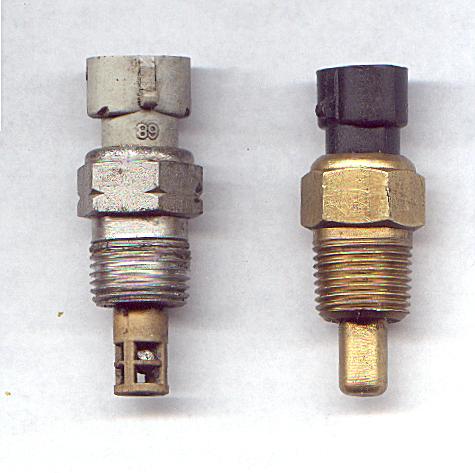
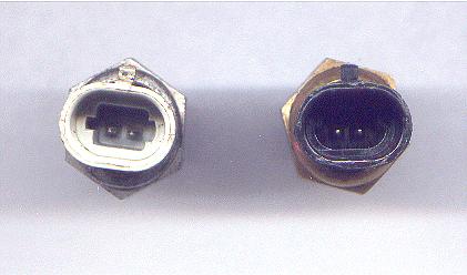
Note that these sensors have different connectors. The coolant temperature sensor uses a “mushroom” shaped key way where it inserts into the sensors, while the open element intake air temperature sensor uses a “rectangular” connector key way.
The wiring schematic for DB37 shows only one input for all of the sensors (except for the two for the TPS). The recommended GM sensors all have two wire connectors. The missing connection is a ground wire for the sensor. Sensor grounds should be brought to the same grounding point on the engine block as the MegaSquirt ground, unless they are grounded through the body of the sensor.
If you are looking for sensors with a standard “spade” type connector and a ground through the body of the sensor (not recommended, see above), GM part number 25036135 is what you need - see the illustration below:
(There is also a spade type GM sensor with a ¼" NPT thread available as GM part number 25036292. This part was originally used as an oil temperature sensor on 84-87 Corvettes, and has the same resistance curve as other GM sensors.)
The resistance curves for the MegaSquirt®/General Motors coolant and air temperature sensors, as well as various part number cross-references, are listed below:
Degrees F | Degrees C | Ohms |
-40º | -40 | 100,700 |
0º | -18 | 25,000 |
20º | -7 | 13,500 |
40º | 4 | 7,500 |
70º | 21 | 3,400 |
100º | 38 | 1,800 |
160º | 71 | 450 |
210º | 99 | 185 |
The thread for the recommended General Motors (and equivalent replacement) coolant and air temperature sensors for the MegaSquirt® controller is 3/8 inch National Pipe Taper [NPT] thread. A 9/16 inch pilot hole is required for the tap. Recall that pipe sizes are based on nominal inside diameters, not outside diameters as for standard National Coarse [NC] and National Fine [NF] threads. The sensors are designed to be tightened to 20 N-m (15 lb·ft).
Nominal Pipe Size | Approx. Outside | Drill Size |
1/8" | 3/8" | 5/16" |
1/4" | 1/2" | 7/16" |
3/8" | 5/8" | 9/16" |
These sensors were been used on practically all GM cars in the 1980s and are easy to find - the same is true for the correct connectors. However, other sensors can be used if the EasyTherm software is used to recalibrate your MegaSquirt® EFI controller.
If you are using non-standard coolant and/or air temp sensors with a MS-I™ controller, you must create “.inc” files that are essentially look-up tables for your MegaSquirt® EFI controller to relate resistance to temperature (For MS-II™ you can change the curves directly in TunerStudio, with no other steps necessary). These files must then be compiled into one .s19 file, and then down loaded to the MegaSquirt® controller. EasyTherm makes it very easy to use “non-standard” temperature sensors with the MegaSquirt® controller. It does three things that otherwise can be a bit of a pain:
1) It automatically creates the .inc files from 3 temperature/resistance pairs. Entry in degrees Fahrenheit or degrees Celsius is allowed. Non-standard bias resistor values can be entered.
2) It creates the .s19 file using the above data - you do not need a compiler!
3) It downloads this .s19 file to the MegaSquirt® controller via the serial link (once R6 is shorted to enter bootloader mode), and reboots the MegaSquirt® - so you do not need to mess with Hyperterminal.
Do not forget that you need to copy the applicable .inc files that EasyTherm creates to your MegaTune directory after a successful down load.
Note that you do not need EasyTherm with MS-II, you can calibrate the thermistor tables directly in TunerStudioMS (under 'Tools') without reloading code.
To use a MegaSquirt® controller with an air cooled engine, you will have to decide where the best place is for the coolant sensor: in the oil, or on the cylinder head (CHT). There are various arguments for and against using either CHT or oil temperature as the 'coolant' temperature input on air cooled motors. A lot depends on whether the motor is substantially oil cooled or not. Since the CTS input is used for warmup enrichment, you want something that responds fairly rapidly, so this is highly engine-dependent.
For high temperature applications (i.e. air cooled engines with a CHT), in MS-II you can set the #unset EXPANDED_CLT_TEMP by changing:
#unset EXPANDED_CLT_TEMP
to
# set EXPANDED_CLT_TEMP:
Then the upper temperature limit should be 600 degrees F. This is from the INI notes:
; FAHRENHEIT (Expanded/Normal):
;     Low Limit: -40F/-40F
;     High limit: 600F/300F
;     Low danger: 150F/50F
;     Low warning: 200F/150F
;     High warning: 325F/200F
;     High danger: 350F/220F
However, you have to calibrate the thermistor table(s) appropriately.
However, note that the tuning software limits the temperature range. The thinking is that if you are at an extreme it is probably a bad or missing sensor, so it goes to a default value. This isn't a big deal in TunerStudio though, you can change these limits in the ms2ReferenceTables.ini file. You can adjust these limits if EXPANDED_CLT_TEMP is set. Currently only the CLT sensor respects EXPANDED_CLT_TEMP, the IAT does not.
IAT min = -40, max=350 if outside that range it goes to 70 CLT min = -40, max=350 if outside that range it goes to 180 CLT with EXTENDED_CLT_TEMP min = -40, max=400 if outside that range it goes to 350 default
Here is the section of the ms2ReferenceTables.ini file that controls that:
; tableLimits (optional) = intentifier, min, max, defaultVal
; will set the default value if value is outside the min and max limits.
tableLimits = 001, -40, 350, 70
#if EXPANDED_CLT_TEMP
tableLimits = 000, -40, 400, 350
#else
tableLimits = 000, -40, 350, 180
#endif"
So the user can just edit the one line in ms2ReferenceTables.ini using notepad.exe or something similar to change it from:
tableLimits = 000, -40, 400, 350
to something like:
tableLimits = 000, -40, 600, 350
or similar, and it should work once the user re-burns the table.
The additional problem with very high temperatures is that the difference in voltage gets very small (and MegaSquirt can only read discrete voltage steps, about 5 milliVolts per step from 0.00 to 5.00). Also, if the volts at the processor pin gets very near 5.00 (~4.98) the values defaults to a safe value because it assumes there is an open circuit.
The ADC count result from the voltage divider circuit (above) is:
ADC Count = V/Vs = ADC max count * (Rs/(Rb+Rs))
= 255 * (Rs/(Rs+2490)) for a MS-I (8-bit ADC)
= 1023 * (Rs/(Rs+2490)) for a MS-II (10-bit ADC)
One thing you can do is use a lower bias resistor (R7 for the CLT circuit) - this will give you more resolution at the high end of the temperature scale (but loose it at the cold end). The default value is 2.49K Ohms, and if that is what is in there you might try 2.2K Ohms or less (down as low as 1.0K). Note that you have to re-calibrate the thermistor tables when you change resistor values.
Here is a simple ADC count calculator that shows the number ADC steps for a given bias resistor and sensor resistance. If the ADC count values are very high or very low at your sensor's resistance (at a given temperature), the temperature range may be restricted:
For air-cooled use, side of the argument says to use the CHT over the oil, as the oil takes over twice as long to get to operating temperature than water in a water-cooled car does. The engine does not need to run rich for long periods, only enough to keep the car driveable while it is warming up. Once the cylinder head is up to temperature, the car is usually quite driveable. For an air cooled engine you can drill and tap into a fin in the head for the CHT sensor.
The other side of the argument says that it does not matter if the oil warms more slowly, you can just set the warm-up enrichment to come off at a lower temperature. In that case, the GM coolant sensor fitted in the oil (sump) will work nicely. Search the archives for extensive discussions on these points. It is your decision.
The MegaSquirt® controller uses the throttle position sensor (TPS) to determine when the engine is at or near full throttle (to shut off feedback from the O2 sensor), when the engine throttle is opening or closing rapidly (and needing an accel/decel enrichment), and when the engine is flooded and needs to be cleared. Some people have managed to make their engines function reasonably well without a TPS. This is not recommended with the standard code, however.
You will need a TPS that is really a potentiometer and not a switch. Many older cars had idle or WOT position switches instead of a real TPS. A real TPS gives a continuously varying signal with changing throttle. There are two wires on the external wiring schematic that go from MegaSquirt® into the TPS sensor. These two MegaSquirt® wires are +5 Vref signal and a sense line. There is a third wire going to ground. Assuming that you have a proper potentiometer TPS, then +5 Vref goes to one side of the pot, the other side goes to ground and the sensor line is hooked to the wiper.
To hook up your throttle position sensor (TPS), disconnect the TPS, and use a digital multi-meter. Switch it to measure resistance. The resistance between two of the connections will stay the same when the throttle is moved. Find those two - one will be the +5 Vref and the other a ground. The third is the sense wire to the MegaSquirt® controller. To figure out which wire is the +5 Vref and which is the ground, connect your meter to one of those two connections and the other to the TPS sense connection.
If you read a high resistance which gets lower as you open the throttle, then disconnected wire is the one which goes to ground, the other one which had the continuous resistance goes to the +5 Vref from the MegaSquirt® EFI Controller, and the remaining wire is the TPS sense wire.
The throttle position sensor is used for flood clear mode and EGO enrichment, as well as accel enrichment:
Use the "Tools/Calibrate TPS" function in MegaTune to ensure that you have an ADC count value well below 155 at closed throttle, and above 178 at wide open throttle (WOT). This will ensure that you are not in flood clear mode while cranking (ideally, your TPS at closed throttle will be 20 or less), and yet still able to activate flood clear mode. Many TPS are adjustable by loosening the screws and rotating it a bit. Also verify that the ADC count increases as you open the throttle, otherwise you have the TPS wired backwards. You should recheck the TPS range each time you change the idle position or reassemble the throttle linkage.
For stepper motor idle control or pulse width modulated idle control with a MegaSquirt-II™ controller, see this page.
The fast idle solenoid is an open/close solenoid vacuum control valve to admit more air when cold. Unlike a cold start injector, it does not handle fuel at all, only additional air. The fast idle solenoid is not the same as an IAC motor, or anything that is controlled like a stepper motor. It is either open or closed. The fast idle solenoid is an off/on electrically controlled vacuum “leak” that speeds the engine RPM for cold starts. Such solenoids have been used often in modern cars, frequently to control EGR valves.
The fast idle solenoid takes clean air from the air cleaner and allows it to bypass the throttle and go directly into the intake manifold. This does not cause a lean condition [as it would with a carburetor] since the MAP sensor adjusts for the “extra” air.
The fast idle is simple. There are simply too many different stepper motor types out there (General Motors uses bipolar, some Chryslers use unipolar, others use PWM proportional control, etc., etc.) to manage with a simple solution. Also, the control of all of the different types of IAC motors out there would be a support nightmare.
SDS sells a air bypass valve which you could use for a fast idle solenoid. The price is ~$70.00 - look for fast idle solenoid; on their specifications page. However, the Fast Idle Solenoid that SDS sells appears to be the same thing as the Solenoid-actuated 3-Port Fuel Tank Selector Valve that J.C. Whitney sells for half that price under P/N 81ZX2686W.
There are some possibilities for the fast idle solenoid from the NAPA catalog:
2-2307 | EGR Solenoid | (91-93 Buick, 88-93 Chevy) | $28.19 |
These all have separate inlet/outlet that looked usable for rubber hose connection. You may be able to get one at a wrecking yard.
There may be an idle speed screw in the throttle body that is blocked by a small metal plug. Remove that plug and you will see a conventional idle speed screw. It is easier to make fine adjustments in the field with this screw than it is with the IAC.
If you are using a Relay Board, note that your FIdle valve can be wired into the Relay Board in two ways. It can take 12 volts from the relay board, and be grounded at the solenoid or at any common ground, OR it can be fed 12 volts from a switched supply (separate from the relay board) and then be grounded by the relay on the Relay Board when the DB37 connection causes the relay to close by providing a ground.
The first instance supplies 12 volts when MegaSquirt® wants FIdle activated. The second instance supplies a ground when FIdle is activated (mimicking the DB37 pin).

If you are designing you own wiring system and using an 'off-the-shelf' vacuum solenoid with two wires, you can do it either way, so long as the solenoid isn't grounded through the case.
On the relay board PCB, there is a spot with three holes in a silkscreen box, and a G and V beside it. This is between the two relays nearest the DB37 end - it is marked J1. This is the jumper location. To select ground or 12 Volts for your FIdle, you solder in a wire from the center hole to either the hole at the G end, or the hole at the V end.
For example, some solenoids have only one wire, and are grounded through the case, so they must have the relay board supply 12 volts.
In this case set the jumper to 'V'. This is the most common option, unless you are converting a previously injected engine which is wired for 'active ground' and you wish to use the existing fast idle valve and wiring (though most EFI engines don't have a FIdle valve, they have a stepper motor, which won't work with MegaSquirt® in any case).
Some people have been using an auxiliary air regulator for fast idle control. SAAB, VW, and many other European vehicles used this system on their early EFI systems (D-jetronic) and on their mechanical injection system (CIS). The great thing about this system is that it does not need to connect to MegaSquirt® at all. You just hook up 12 volt, ignition switched, and you are ready to run. Use 12 volts from the fuel pump relay. If the engine is not actually running you do not want it powered up, as it will move to the 'warm' position even though the engine isn't running.
Mount the regulator to the engine such that engine heat can keep the valve closed when you do not need any additional air for warmup. During cold starts, the auxiliary air valve opens to allow additional air into the inlet duct. As engine heats up, a bi-metallic element expands and closes valve. At approximately 140°F (80°C) the auxiliary air orifice is completely closed by the valve.
For ignition triggering with MegaSquirt-II, see this page.
In most cases, you can just hook the MegaSquirt® controller's tach signal wire to the tach pin on your ignition and it will work fine.
For some installations, however, getting a decent tach signal may require some trial and error.
Now, with that said, almost all of the people experiencing tach problems have worked them out by experimentation with different components or alternative trigger methods. Does not seem to be the most direct method, but with so many different setups out there, it is the only thing that can be done. Things to try if you experience tach noise:
1) Before anything, make sure that the ignition system is up to snuff - good plugs/wires/coil/grounds/etc.
2) Some installations have reported problems with low rpm spikes when triggering directly off the coil's negative terminal (i.e., not controlling ignition timing). Typically this sees the reported rpm at 1100 rpm jump to 5000+ rpm for short periods. This can make idle and off-idle tuning difficult. To fix this, add the “Dave” capacitor. This is a 0.22µf cap across the junction of D5/R10 to XG1 on a V2.2 main board. The V3 main board has the Dave capacitor 'built in' as C30.
Suitable capacitors include:
Digi-Key Part Numbers for the “Dave” Cap C31 | |||
EF2224-ND |
0.22µF, 250V |
METAL POLY CAP, ±10%, Radial |
$0.54 each |
BC1828-ND |
0.22µF, 250V |
CAP FILM MMKP, ±5%, Radial |
$0.59 |
BC1779-ND |
0.22µF, 250V | CAP FILM MKT, ±10%, Radial |
$0.269 |
P11118-ND |
0.22µF, 250/300VAC |
CAP INTER SUPP, ±20% |
$0.61 |
Many other capacitors can be used, including 0.33µf. People have used capacitors rated as low as 50 volts, however higher rated caps with better withstand the voltage spikes of up to 120 Volts that can appear in the tach signal.
On a V2.2 mian board, solder one leg of the Dave cap to the XG1-XG2 jumper, and solder the other leg to the end of R10 furthest away from the web address on the silkscreen (i.e. the "top" of the board when you can read the text).
3) If you are triggering off the coil negative terminal, you may wish to duplicate the V3 main board circuit for use with the negative coil terminal by adding a 22 Volt Zener diode in series (banded end towards the coil negative terminal) into the tach input wire to DB37 pin #24. This will filter all of the oscillations and noise in the coil that are less than 22 Volts (and triggered only on the induced voltage spike when the coil fires). In rare cases you might need more than 22 Volts - you can use Zener diodes in series (all bands towards the coil - term.) - the overall rating is additive. For example, two 5.6 Volt Zener diodes in series with a 22 Volt Zener diode is equivalent to 22 + 5.6 + 5.6 = 33.2 Volts (assuming they are installed correctly, of course!)
You can also try Peter Florance's trigger filter. It uses:
Instruction and schematics are in the download section of the forum, at Peter Florance Tach Circuit (.PDF).
4) If you are running a VR (variable reluctor) sensor, you an use the VR input circuit on the V3 main board. For a V2.2 board, to use a VR input, one method that works nicely is to use a 4-pin HEI module as a trigger. You use this in parallel with the existing HEI module, in that the VR sensor wires hook up to both modules. The new module is used to generate tach signals to the MegaSquirt® EFI controller only.
NAPA OnLine sells the 4-pin HEI ignition module, ECHTP45, for ~$39 + shipping. These are also widely available as Wells DR100, Niehoff DR400, Standard part numberLX-301 (~$28); or AC DELCO D1906 (~$33), and were used on many non-computer GM V-8s, V-6s and I-6s from 1975 to the mid 1980s.
Here is how to wire it up. The four HEI module terminals are labeled W, G, B and C.
W and G; hook up to the VR sensor (parallel with the existing module). Hook a 470 ohm, 1/2 watt resistor between terminal B and C. Hook terminal B to a switched +12V supply. Hook C to the tach lead on the MegaSquirt box. Be sure to mount the HEI module such that the metal bottom is connected to ground (either engine or chassis). The module will not get hot, since there is not much load (the resistor), but the metal still needs to be grounded. In the MegaSquirt box, be sure there is the Wing diode (no John Zener) and Ed capacitor (try 0.001mf).
This trick works for pretty much any VR ignition system - it does not have to be a GM, pretty much any VR sensor will drive the HEI module. And the HEI module presents a high-impedance to the VR sensor circuit, so you can parallel with an existing ignition set-up without harm. It is possible to trigger off of the (-) terminal of the coil, and in many cases it is successful - Bruce has been running this way for a year, so have others. But, there are some applications that the trigger will be noisy - and, unfortunately, it is impossible to predict ahead of time which vehicles will be the noisy ones -what works on one car will not work on another car, even the same make/year.
5) Change the value of the Ed capacitor (C12 on a V3 or V2.2 main board) - from 0.001mf to 0.1mf. The higher value capacitors will reduce more of the noise through “averaging”, but may inhibit higher RPM trigger due to too much averaging.
6) For a few ignitions, varying the 390 ohm resistor (R12 on a V3 main board, R10 on a V2.2 main board) up to higher values, up to 10K (or more in some installations - consult the MSEFI.com Forums), may also reduce the noise in some cases. It is not possible to predict in advance what value will work with which ignition.
7) If there are processor resets, then running the opto-isolator LED return back to the engine ground via a dedicated wire may solve this. The appropriate assembly guide for your main board has details on this. For more information on resets, see this.
8) It has been reported that running shielded cable back to the ECU for the tach signal will help a great deal for some installs.
9) For tach spikes where you are controlling the ignition timing, it's likely that the coil is introducing noise into the line. This could be because the coil shares common power and/or ground with the MegaSquirt® EFI controller's input circuit, or it could be electro-magnetic interference. Some things you can try are:
For Hall sensors, taking the signal right off of the hall sensor works nicely. The value of the pull-up resistor, as well as the 390 ohm series resistor, may need to be adjusted. There are plenty of people on the msefi.com forums with experience on how to do this.
There is a big difference between these two types of sensors.
The VR sensor is an induction type sensor, it is passive;, i.e. it does not require a power source, and has a small magnet built in. It basically works like a dynamo. The output of this sensor varies with the speed of the engine. At idle the output is approximately .6 volts, at mid RPM it is closer to 3 volts, and at high revs it goes to almost 50 volts. You have to keep in mind that this type of sensor produces an AC output. The pulse is positive when the pole is approaching, and negative when the pole is leaving (provided you have the right polarity). The simplest way to see this is by hooking it up to a cheap analog voltmeter and using a wrench or other non magnetic - soft iron; piece of metal. When you put the metal piece on the sensor the needle on the voltmeter will swing one way. When you quickly remove it the needle will swing the other way.
A Hall sensor is an active magnetic field presence sensor. It is based on the Hall effect, that is a semiconductor changes its resistance in a presence of a magnetic field. These types of sensors require a flying magnet wheel. Instead of teeth on the wheel you must have small magnets. This type of sensor has an electronic circuitry built inside and thus provides a constant voltage pulse regardless of the speed. The sensor is also sensitive to the polarity of the magnet. N pole will turn it on, S will not, or vice versa dependent on the orientation of the sensor. The pulse produced is as long as there is a magnetic field of some strength present, and is always of the same polarity (positive with respect to ground).
VR sensors are cheap and very rugged, Hall effect sensors are much smaller, more expensive, and nearly as rugged.
If you cannot get any of the above suggestions to work, then another trigger source, like an external VR sensor with a crank wheel, will work. This will require more work on the user end, but if the situation leads you to this, then this is all that can be done.
MegaSquirt cannot handle a capacitive discharge ignition (CDI) output directly. The CDI primary voltage is around 400V. Either uses a tach signal or the VR/points input.
To fix this, pick up a length of 3/32" (~2.5mm); hollow brass tubing at the hobby shop - used in model R/C work. Cut off a piece long enough to run out of the back. Then use a flare tool to make a small lip on both ends to act as a barb. You can then hook it up with a short piece of vacuum tube, and ran the brass tube out the back panel.
Or you can insert the rubber (or vinyl) MAP-Bulkhead tubing in a short length of heat shrink tubing before installing it, and shrink it carefully once it is in place. This insulates the tubing, and holds the tubing tighter on the barbs. You can also use it to hold it on the barbs on both sides of your bulkhead fitting. Heat shrink tubing is non-conductive [by design] and relatively resistant to puncture and abrasion. Choose an appropriate size so you do not collapse the tube.
If your MegaSquirt® EFI controller works fine on the stimulator, but the runtime display shows that both the air and coolant temperatures are 170°F and the TPS is at 100% when installed in the car with a relay board, you need to check the sensor grounds.
On the relay board, the grounds for the coolant temperature sensor, air temperature sensor, and TPS are all brought in separately through pins 14, 17, and 19 (on JP1), and feed pin 19 of the DB37. They then travel through a wire connecting the pins 19 at either end of the cable. At MegaSquirt® EFI controller, the pin 19 sensor ground is joined to a common ground on the PCB with all of the other ground pins (pins 1-18). Pin 19 of the DB37 MUST be grounded if your sensor grounds are brought back to the relay board as designed.
The relay board cable is designed to have a return wire that goes from the relay board DB37-pin 19 to a common ground on the MegaSquirt PCB. If you do not have this wire in your MegaSquirt/relay board cable, you need to connect the sensors to ground. You can do this by:
In both cases you will need three temperature resistance pairs. The most convenient way to do this that is reasonably accurate is to measure the resistance of the sensor at room temperature, in ice water, and in boiling water to get the temperatures at 32°F (0C), and intermediate temperature, and 212°F (100C).
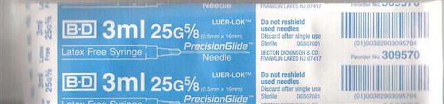
The way to test the MAP sensors is with a syringe - hook it to the MAP line and see if you get over 250. Below is a scan of the label from the syringe know to work, so you know what to ask for at any drug store (though virtually any syringe will do). Take the needle off and screw the syringe directly into the vacuum line, then compress the syringe and you should get 'boost'.
You should also see about ~85-100 kPa in TunerStudioMS at rest (depending on your elevation and the weather conditions), and 250+ kPa at maximum pressure (which you should be able to achieve by hooking the syringe up fully extended, then compressing it) so check that.
Check that you have 5.0 Volts on pin #3 of the MAP sensor (counting from the square solder pad), and ground on pin #2 (less than 1.0 Ohms resistance to the middle lead of the voltage regulator).
At normal sea level, the MAP sensor signal on the board (pin #1, the pin closest to D4) will be 1.75 to 1.80 volts. With the syringe fully compressed (but not bottomed out), you should be able to get at least 4.90 volts from the MAP sensor signal pin. If not, touch up the soldering on the MAP sensor pins.
The MAP sensor signal goes directly to the CPU (through R2) on pin #23 (near the inductors). So check that you are getting the same voltages as above on CPU pin #23. If you don't, recheck the soldering on pin #23, the resistor R2, the capacitor C4, and make sure that the diode D1 is not installed.
These are set on the enrichments window of TunerStudioMS.
It is also possible for a too rich mixture to result in cool exhaust gas temperatures that cause the sensor to read low (as it would during warm-up).
However, if you lean the engine down enough for the O2 sensor to read rich, and then keep leaning it - the sensor should eventually read lean.
In the meantime, disable O2 sensor feedback by setting the EGO step (%) to zero on the TunerStudioMS enrichments page to prevent very rich mixtures that confuse your tuning efforts.
To do this, lift the +12v pin of each of the TIP125's in the flyback circuit. The TIP125 are Q9 and Q12 (the ones with the mica insulators) on a V3 main board. The 12V pin on the TIP 125 is the pin in the middle - melt the solder and pull the pin up with needle nose pliers. Then run a wire from each of the pins you pulled up independently back to the raw +12v supply (outside of the box), and before the noise filter. You can ran the wires through the spares (SPR3 and SPR4, which go to DB37 #5 and #6) on a V3 main board. 20 gauge wire is fine.
Here is a little explanation on the flyback during PWM.
The top drawing A shows the current when the injector driver is on, during the high-time of the PWM waveform. Basically the FET is turned on, energizing the injector. This is the PWM high time, and it depends on the setting of the PWM duty cycle.
The second drawing B is the path when the driver is turned off during PWM flyback damping, or recirculation mode. This occurs during the off time of the PWM current limit. During this time the injector is trying to maintain the current that was there during the PWM on time (see Lenz law). So the injector will generate a current (from the collapsing magnetic field) that flows thru the FR302 diode, the TIP125 transistor, thru the +12V feed and back to the injector. The +12V feed to the MS is used as a path. Note that this is the closed loop path, this is not ground-referenced - the +12V is used as a return path, not as the potential source.
Now if the +12V line has resistance, then this current path will cause a voltage drop across the line - Ohm's law. If you have ever used one of those portable lights on the long extension cord with the built-in socket (trouble-light) and ever ran a tool from this outlet, you may notice that the light bulb dims down whenever the tool is active. This is due to the resistance in the extension cord wiring, and by drawing more current the wire drops some of the available voltage, and this is seen in the light. More current means more voltage drop for a given resistance. Now if the extension cord is a large-gauge wire then the voltage drop is less.
The same thing applies here in the +12V line. Depending on the path of the current thru the +12V wiring from the raw +12V MS feed back to the injector +12V feed there are many places where could be potential voltage drops. Things like small-gauge wire, resistance in contacts like relays and MS connector, etc. can all add up.
You can also use the separate +12V lead just for the flyback. The flyback damp +12V is on the bottom of the PCB. This trace could be cut and ran thru a spare connector output. Best bet would be to run this wire direct to the injector +12V source in order to complete the damping circuit and to separate this from the MS +12V source.