MegaSquirt-II™ controllers can be triggered from the negative terminal of the coil, just like MS-I, as long as MS-II™ is not being used to control the ignition timing. However, if you are controlling the ignition timing, then the tach signal must be fixed with respect to the crank position (not vary with the advance timing like the coil signal).
Most modern electronic ignitions use one of three types of sensors in the distributor (or crank position sensor). They use either a variable reluctor (VR) sensor, a hall sensor, or an optical sensor.
Variable reluctor sensors are cheap and very rugged, Hall effect sensors are much smaller, more expensive, and nearly as rugged.
There are some differences in the signals these three types of sensors send to MegaSquirt-II™. The Hall effect, optical, and points systems produces a similar signal - a square wave of constant amplitude, polarity, and duration (in engine degrees). However, the variable reluctor sensor produces a sinusoidal (alternating current) wave form (with both + and - components) whose amplitude varies with rpm. This signal can be processed by an ignition module to produce a square wave suitable for input to MegaSquirt-II™.
The Variable Reluctor (VR) sensor is an induction type sensor, it is "passive", i.e. it does not require a power source, and has a small magnet built in.
The sensor uses a magnetic pickup to produce a signal. A core of steel is wrapped with hundreds of turns of fine wire at one end. A small magnet is attached to the other end, and this assembly is mounted in the distributor facing the distributor shaft. When a notch, pin, teeth or hole in a timing wheel (the reluctor) moves past the sensor, it causes a change in the magnetic flux field around the sensor. As the teeth of the reluctor approach the coil assembly, the flux from the magnet is pulled in close to the bar. The sudden field change induces an electrical current in the coil, which is then converted to a voltage signal by electronic circuitry in MegaSquirt-II™. As the teeth move away, the flux springs back outward, inducing a voltage in the pickup coil. This induced current has reversed direction as the magnetic field returns to normal.
The result is an alternating current (AC) voltage that reverses polarity and crosses zero as it the pin aligns with the sensor. The output voltage of this sensor varies with the speed of the engine. This voltage is then chopped/filtered/amplified and used to drive a high voltage/high current transistor that switches the coil current. This signal is used by MegaSquirt-II™ for ignition timing as well as injector timing in engines with sequential fuel injection.
The variable reluctor sensor has been the most widely used in automotive ignitions. It has been used by virtually every auto manufacturer for many years and is still widely used. The GM high energy ignition (HEI) is one example. It is a rugged, reliable system that holds up well in a high temperature, high vibration environment. Because it generates a signal without requiring external power, it is very easy to implement. The magnetic variable reluctor sensor is gradually being phased out in modern automobiles, however, because it has limited ability to sense teeth that are very close together, which is necessary to gain the positional accuracy required by modern engine management systems.
At idle the peak output is approximately 0.6 volts (but could be lower, or higher, than that), at mid-RPM it is likely close to 3 volts or higher, and at very high RPM it might go as high as ~50 volts. This type of sensor produces an alternating current (AC) wave output. The pulse is positive when the "pole", is approaching, and negative when the pole is leaving (if you have the right polarity). The simplest way to see this is by hooking it up to a cheap analog voltmeter and using a wrench or other "non magnetic - soft iron", piece of metal. When you place the metal piece on the sensor the needle on the voltmeter will swing one way. When you quickly remove it the needle will swing the other way.
Magnetic sensors can be checked by unplugging the electrical connector and checking resistance between the appropriate terminals. On the Rover 820, for example, the sensor should read between 1200 and 1450 ohms. Others could be 400 Ohms or lower. For instance, the VW AEB 1.8 turbocharged engines specify a resistance of 400 to 1000 Ohms. But you should never get
A magnetic crank position sensor should also produce an alternating current when the engine is cranked so a voltage output check can be performed. With the sensor connected, the output voltage across the appropriate module terminals while cranking the engine should be at least 20 milliVolts (mV) on the AC scale of your meter for you MegaSquirt® controller to operate properly. Check the manual for your vehicle for the specified acceptable voltage range for you particular crank wheel/sensor setup.
In general, the most suitable option for controlling ignition timing advance on a distributor with a VR sensor on MegaSquirt-II is using the VR sensor circuit built into the V3 main board (see step #51 and #52 here) and the high current ignition driver circuit on the V3 main board to control the coil. With the V2.2 main board, you can use a GM 7 or 8-pin HEI module to convert the signal AND control the coil. There is much more on this on the GM HEI page.
A variable reluctor magnetic sensor typically has two wires, and possibly a shield wire. One of these will go to the VR circuit input (DB37 pin #24) the other to ground. The sensor wiring will affect the signal seen by the VR circuit, and hence the processor.
If you swap the wires from the sensor (so the one previously used as the trigger is grounded, and the other - that was grounded - is used as the signal for the VR circuit) then the trigger point will now be the negative-going zero crossing, and the setting in MegaTune should be changed to 'rising edge'.
Changing any one of these (VR polarity, ignition input capture edge) changes the actual trigger point, so the timing should be 're-calibrated'. However, if you change both - you should be where you started (whether that was right or wrong!).
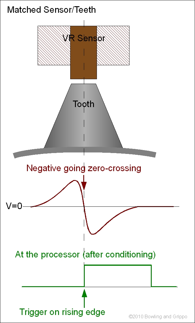
There are two zero-crossings per tooth - a steep crossing occurs when a tooth passes, the other 'shallow' crossing occurs between teeth. Note that only one 'zero-crossing' is appropriate for triggering, this is the steep crossing at the tooth (the other zero-crossing is relatively flat, and so the timing of it is quite variable compared to the proper trigger). The wrong edge may be so variable that MS-II considers the signal out of range, and rejects it altogether.
So the VR polarity is a relative thing, and needs to be correct (on the steep edge of the signal) and set to work with the ignition input capture 'rising/falling edge' setting.
How do you know which is the correct edge to trigger on? Here are three ways:
Note also that best bet is to obtain an OEM matched wheel and sensor set whenever possible. If the wheel won't fit, by all means make your own wheel, but with the exact same tooth type, so you know it will be matched to the sensor. Don't just grab a Ford sensor and a Honda wheel and expect them to work with each other.
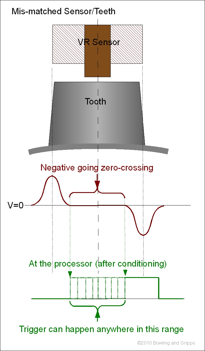
The most important consideration for a VR sensor is that the tooth width (not the wheel thickness, but the length of the top of tooth in the direction of travel) should be matched to the sensor tip width (not the overall all width of the sensor, just the sensing element which is usually visible at the end). The correct width will help provide a sharp zero-crossing transition, making the timing predictable.
A tooth that is too long will 'spread out' the zero crossing, making the zero-crossing unpredictable, causing timing 'jitter'.
(Note that there is a possibility of the opposite situation - the sensor being much wider than the teeth. This might happen if you try to squeeze a very small multi-tooth wheel inside a distributor, for example. Having the sensor tip wider than the teeth is definitely not good either, as the signal will be weak, subject to noise, and very likely unusable.)
Without doing a lot of testing, the safest assumption is that the ideal tooth is a right triangle shape with the tip just slightly blunted (to about 1/8" or 3mm on the flats) by a lathe to make it a little safer and true it all up. The right triangle provides a slow up ramp, then the right angle side provides a very sharp vertical drop - which is what you want to minimize the crossing location error.
The spacing between the sensor tip and tooth is important. The VR sensor output voltage output is highly dependent on the proximity of the sensor to the passing teeth.
Also, note that the V3 main board's VR input circuit has a couple of adjustments that can be used to eliminate noise, see: www.megamanual.com/ms2/vradjust.htm
A Hall effect sensor is an "active", magnetic field presence sensor. It is based on the Hall effect. The principle was discovered in 1879. When Edwin H. Hall applied an current to a piece of metal inserted between two magnets, he found it created a secondary voltage in the metal at a right angle to the applied voltage. In the sensors we are concerned with, the Hall effect is used to change of resistance in a semiconductor in a magnetic field, and this is then used to switch an output voltage from high to low, or vice versa.
The Hall effect sensor consists of semiconductor material which will conduct current when the material is subject to a magnetic field. These types of sensors require a "flying magnet", wheel. Instead of teeth on the wheel, as in a variable reluctor sensor, you must have small magnet and a shutter wheel.
The Hall effect sensor consists of three parts:
A Hall-Effect element consists of a wafer of silicon through which a current is passed. When a magnet is placed in proximity to the wafer, the current tends to bunch up on one side of the silicon. This concentration is amplified and detected, indicating the presence or absence of a magnetic field. When a window (vane) of the shutter wheel is in line with the Hall element and the magnet, the magnetic field expands to reach the element and no voltage is produced. When there is metal between the Hall element and the magnet, the magnetic field is blocked from reaching the element and a voltage is produced.
The Hall sensor has electronic circuitry that provides a constant voltage pulse regardless of the speed. The square wave it produces is particularly suitable for use in digital electronic systems. The sensor is also sensitive to the polarity of the magnet. North pole will turn it on, South will not, or vice-versa, depending on the orientation of the sensor. The pulse produced is as long as there is a magnetic field of some strength present, and is always of the same polarity (positive with respect to ground).
There are many advantages to the Hall effect sensor. Since it is an integrated circuit, it can be made very small with a number of features at minimal cost. It exceeds all current automotive temperature specs. Its accuracy is unaffected even when covered in under hood muck. Hall-Effect triggering has been widely used on European vehicles with Bosch electronics since the late 1970s. It has been used in the U.S. as early as 1975. In the 1980s it became more common, mainly on Chrysler imports. Ford was the first domestic manufacturer to embrace the technology with the advent of the TFI (Thick Film Integrated) ignition.
Hall-Effect has become popular sensor as a camshaft position sensor. There are a few reasons for this:
Hall effect crankshaft position sensors typically have three terminals:

The sensor must have voltage and ground to produce a signal, so check these terminals first with an analog voltmeter if you suspect it is not working. Sensor output can be checked by disconnecting the coil and cranking the engine to see if the sensor produces a voltage signal. The voltmeter needle should jump each time a shutter blade passes through the Hall effect switch.
You can use the LED tester to check the signal. it should blink as the distributor is rotated:
On an oscilloscope, you should see a square wave form:
A Hall Effect Sensor may be normally “high” or normally “low ”, depending on how it is designed. The normally “high” variety (such as GM crank position sensors) produce a steady voltage (equal to the supply voltage) when the magnetic window is unobstructed. The voltage output drops to near zero volts when a blade enters the magnetic window and blocks the field. The Profile Ignition Pickup (PIP) and Cylinder Identification (CID) Hall sensors found in Ford distributorless ignition systems work in the opposite manner. When the shutter blade blocks the magnetic field, the output signal goes from near zero (low) to maximum voltage (high).
In some cases, the Hall sensor doesn't produce a voltage signal, instead it pulls a voltage low. In these cases, you will need to attach a pull-up voltage and current limiting resistor to the signal line. You do this with a 5 or 12 Volt source (MegaSquirt will work with either voltage, check your sensor specs to see which it expects).
In general, the most suitable option for controlling ignition timing advance on a distributor with a Hall sensor on MegaSquirt-II is the high current ignition driver circuit on the V3 main board, or the Bosch 0 227 100 124 module to control the coil on a V2.2 main board. There is much more on this on the Bosch 124 page.
Optical (a.k.a. photo-electric) sensors include:
In general, the most suitable option for controlling ignition timing advance on a distributor with an optical sensor on MegaSquirt-II™ is the high current ignition driver circuit on the V3 main board, or the Bosch 0 227 100 124 module to control the coil on a V2.2 main board. There is much more on this on the Bosch 124 page.
The Kettering 'points' type of ignition used a distributor as a mechanical switch to turn the primary circuit on and off. An arm with a set of contacts was controlled by a small cam inside the distributor to control the current from the ignition coil’s primary circuit. One point contact is connected to ground, the other point contact is connected to the coil's negative terminal. The points ground the coil's negative terminal (allowing current to flow from the 12V source) to charge it and then open to fire.
The result is that the points produce an approximately square wave signal (on the point connected to the coil negative terminal), with an 'amplitude' of 12 volts when they are open), pulled to ground when they close (charging). By replacing the coil with a current limited pull-up circuit, we get a much cleaner signal that is not electrically demanding on the points (so they last much longer).
This type of switching has not been used in ignition system by manufacturers for many years. In these cases the distributor also mechanically adjusted the timing, though MegaSquirt-II could be used with a points type distributor by locking the mechanical and vacuum advance mechanisms.
To use a point type signal for MegaSquirt® and advance timing control, you need to:
In general, the most suitable option for controlling ignition timing advance on a distributor with points on MegaSquirt-II™ is using the high current ignition circuit (with V3 main boards) to directly control the coil or the Bosch 0 227 100 124 module (with V2.2 main boards).