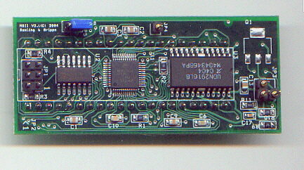
MegaSquirt-II is a plug-in processor card which has the MC9S12C64 processor plus support hardware as well as a stepper motor chip.
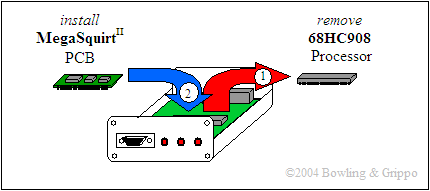
MegaSquirt-II™ is a daughter card that replaces the 68HC908 (MegaSquirt-I™) processor in MegaSquirt®. The end of MegaSquirt-II™ daughter card with the row of three jumpers on it (JP1) goes towards the notched end of the MegaSquirt® CPU socket. Note that if you install it the wrong way around, it will hit the case (or overhang the MegaSquirt® PCB, if it isn't in a case yet).
To Install MegaSquirt-II:
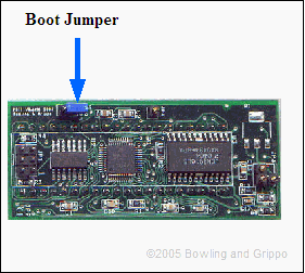
If the jumper is only on 1 header pin, then you also have the operating program loaded, and if you plug in to a main board with a stimulator you should see the injector lights flashing, meaning the program is running. In most cases the jumper will be over both pins. This means only the bootloader program is loaded and you must load the operating program using Eric Fahlgren's downloader program.
The code you will load will depend on whether your is a V1 version (no CAN chip) or a V2 version (w/ CAN). The best way to perhaps determine the MS-II version of any board is that the V1 boards had green LPI solder mask, where as the new V2 boards are now blue solder mask. So MS-II version V1 is green, and the latest V2 (with CAN and the extra memory) is blue. (All MS-II's sold since early 2006 are V2 with the CAN chip.)
If you miss any of these steps, you'll have problem communicating. For more info, see step #40 here:
Next you may need to connect some jumpers.
+12 volts is supplied to MegaSquirt-II from the MegaSquirt® PCB. This is used for the 12 Volt stepper motor driver. You should add a jumper on the MegaSquirt® printed circuit board to provide a source of +12V even if you aren't using a stepper motor (this will keep the stepper driver chip cooler). On a V2.2 main board you run the jumper wire:
On a V3 main board, follow the instructions in the V3 assembly guide.
This is indeed one of the difficult things if one wants to keep on swapping between the old 68HC908GP32 and the MS-II, in that if you re-install the 68HC908GP32, you MUST:
Also, if you are going back to MegaSquirt-I be sure to unplug your stepper motor if you had one connected, because it will confuse and possibly damage your MegaSquirt-I if you don't. It will run for a while and then start resetting madly. This is in addition to the fact that you must unplug the 12V line from the socket before re-installing MegaSquirt-I.
Then you have real plug 'n play between the MegaSquirt-II™ and the 68HC908GP32 from MegaSquirt-I.
This is the one non-plug-n-play setup between the 68HC908GP32 processor (i.e., the MegaSquirt® processor) and the MegaSquirt-II board. The problem is that the MegaSquirt-II needs the +12V, but there is nothing like this running to the DIP40 socket for the 68HC908GP32 (for obvious reasons: 12 Volts would cook the GP32).
This is one of the issues Bruce is addressing on the new V3.000 printed circuit board with a pad on pin 16 and a sanctioned +12V source pad.
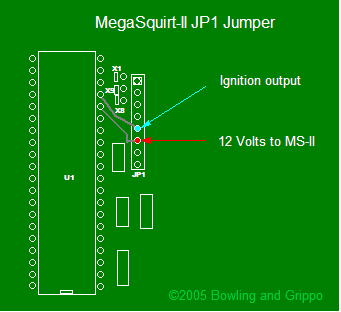
To use the ignition control and IAC control functions of MegaSquirt-II™ on a V2.2 MegaSquirt® PCB, you will need to add wires for these functions, and set a jumper or two. The ignition control wire should be hooked to the 5th pin on the JP1 header (the row of closely spaced holes beside the CPU socket, near the copyright notice). The IAC pins are connected to X2, X3, X4, and X5 (see the illustration below). To bring the connections out on the DB37 connector, you will need to add a few jumper wires.
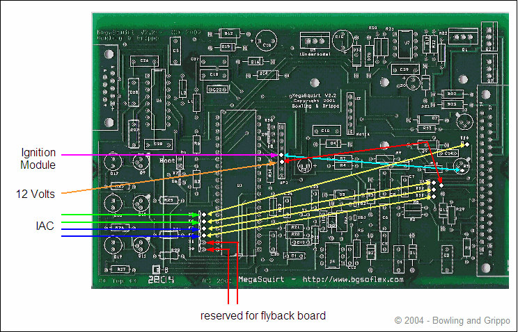
If you want to use the IAC stepper motor control function of MegaSquirt-II with a V2.2 main board, there are some jumpers to hook up on the MegaSquirt® PCB:
Note that the V3 main board has dedicated jumpers for the IAC, see the instruction in step #22 of the V3 assembly guide.
Then you need to select the 'Idle Control/Algorithm' in MegaTune. In some cases setting the stepper motor to "IAC Stepper Always On" will cause the IAC to get hot. However setting it to "IAC Stepper Moving Only", might cause a problem with idle speed changing from one start to another.
You can test if your IAC is suitable for 'always on' by leaving your stepper powered on the bench for 15 min or so. If it doesn't feel too hot to you, then set it to "Always On". Apparently this is what GM does. But if you want to be safe they should test it on the bench for 15 min or so, or monitor it closely in the car while not moving for at least 15 minutes, checking the IAC temperature frequently with your fingers. It may get warm, but it shouldn't burn your fingers just touching it.
There are more details on the IAC page. (These DB37 pins are also used for V3.0 main boards).
If you want to use the ignition control function of MegaSquirt-II™ with a v2.2 main board, you need to connect a wire from 5th hole of the JP1 header (counting from the end nearest X10) on the MegaSquirt® PCB to the ignition module pin that receives a signal. (You should also remove the Dave capacitor, if installed.)
Note that the ignition signal comes in to MegaSquirt-II on DB37 pin #24, as with the standard MegaSquirt.
However, it is important to understand that there are differences between the ignition input signal needed for MegaSquirt-II versus MegaSquirt®:
So you CANNOT use the negative side of the coil to trigger MegaSquirt-II because the coil already has timing advance built in, and using it for a timing signal will screw up the total advance severely. You must use the appropriate distributor or crank wheel for your ignition module.
One other thing to note is that the "Dave" cap will delay incoming ignition pulses. The delay is dependent on frequency. It should be used only if people are tapping an ignition coil primary for fuel-only. For any type of ignition control installation, the input source should be Hall or VR sensor or something else other than the coil primary windings (i.e., the (-) terminal of the coil). So, for these cases, the Dave cap should be eliminated or drastically reduced, or there may be an rpm dependent delay in timing.
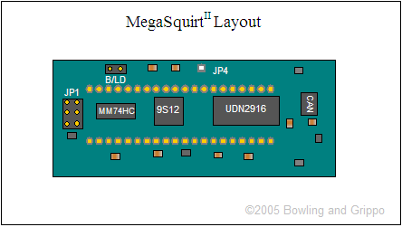
There are a few jumpers and switches on the MegaSquirt-II daughter card. These are:
V3.0 High Current Ignition Driver
If you are using the 'high current ignition driver' on the V3.0 main board to drive a coil directly with MegaSquirt-II, you need to:
See: www.megamanual.com/ms2/vb921.htm for more information.
Installing the Ignition Control System
For info on how to install various ignition systems with MegaSquirt-II™, see their individual pages:
Independent Barometric Pressure Sensor
MegaSquirt-II™ has the provisions for a second independent 'real time' baro sensor. This will update your fueling continuously, which may be helpful if you are climbing the Rocky mountains or running Pike's Peak.
To add an independent baro sensor to your MegaSquirt-II DIY main board (1.01/2.2/3.0), use an MPX4250AP (the standard MS sensor). Run leads from:
You can test your installed MegaSquirt-II™ with the regular stimulator. With the stim, you should see the INJ1 and INJ2 LEDs flash, with the frequency dependent on the setting of the rpm pots. The fuel pump LED should come on and stay on, however the FIdle LED will not come on unless you have chosen the FIdle option in the tuning software.
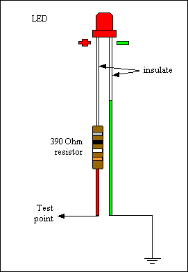
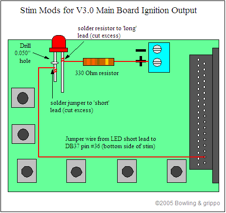
If you want the stim to display the output of the IGBT circuit, you can modify your stim with a 330 Ohm resistor, LED, and a bit of jumper wire. The LED will flash at every ignition event, though this can be hard to see at all but very low rpms (~400 rpm with a V8).
This circuit is especially useful to ensure that your coil is not charging (LED not lit) when rpm drop very low. This prevents the coil from burning up when the ignition key is 'on' but the engine isn't started (when editing parameters in MegaTune for example).
Alternatively, you can wire a stop lamp bulb in place of the coil while setting up, and ensure that it is NOT light while the rpms are zero and the ignition is switched to the 'on' position.
If you have questions, there is a huge amount of collective experience and knowledge related to the assembly and installation of MegaSquirt®/MegaSquirt-II™ in various vehicles available on the MegaSquirt forums.
Installing a Second Ignition Driver for Use with MicroSquirt® Code
If you wish to install a second ignition driver on MS-II™ (to drive two wasted spark coils on a 4 cylinder engine, for example) you need to download the MicroSquirt® code, and add some hardware:
For the second ignition driver, you would have to duplicate the second circuit on MicroSquirt® (with a VB921 (or BIP373), and a 100 Ohm, and 100K Ohm resistors), connected to the microcontroller's PT4 port (CPU pin #7), which is currently used for PWM2 (pin #4 on the MC74HC00M), and would have to be brought off MS-II separately with a jumper wire. (See: www.microsquirt.info/us_hardware.htm). You will want to jumper from the MC74HC00D, as the spacing is very tight on the CPU pins. Pin #1 on the MC74HC00M is nearest the "1" for the 3x2 BDM jumper, and you count the pins counter-clockwise around the IC.
This same pin routing is made on the MS-II daughter board by disabling the PWM traces into the logic chip and routing them to the appropriate output connector pins. The same software will then work in the same way on MS-II and MicroSquirt. It's not a difficult job for someone experienced in this, and would only take a few minutes to do. But it's not something you want to try without practice and the proper soldering iron and solder. If you don't make the mod to MS-II, then do NOT set any of the Dual Spark options - they will not work. But you can use the v2.83+ code with the unmodified MS-II board to get all the other features of this code.
The MM74HC00 NAND gate needs to stay in place on MS-II, but with some mods.
Note that you will want a connector in the second ignition wire from MS-II, as otherwise you won't be able to remove MS-II™ completely from the main board (though you can cut this wire if necessary and solder it back together when reinstalling...)
Also note that you lose the PWM current limiting, so you must use resistors with low impedance injectors.