| |
| |
If you have put your MegaSquirt® together, but it does not work, this section will help you sort out the problems. Often there is something simple wrong, and a few simple checks can identify what needs correcting.
Follow the instructions below. Before checking anything else, make sure your stimulator has a fresh battery - many problems are traced to a low battery voltage, but only after a long, frustrating troubleshooting effort! Also, make sure the CPU is in the correct way. On an MS-I, the notch should be closest the edge of the PCB. On an MS-II™, the 6 pin header should be nearest the edge of the PCB. Before starting, have a look at the schematics and PCB layout PDF files - you may want to print some sections to help you troubleshoot. Read ALL of the troubleshooting tips first, then go through the steps:
Note: With 2.88+ code, the first thing you must do is set the ECU Type (under 'Fuel Set-Up/General') to match your hardware (MS-II = 1 or MicroSquirt® = 2), MegaTune will not let you change anything else until you do this. The rpm will cycle from 0 to 8000 rpm, and most of the menus will be inaccessible. Do not change settings, expect the stim to work, load an MSQ, etc., until you have set the ECU Type (MS-II = 1, MicroSquirt® = 2, the MS-II Sequencer will be 3). This setting applies to MS-II derivatives with code 2.88 or higher code only.
0) Is your stim battery powered? The battery might be dead, as they only last a few minutes while powering MegaSquirt. So replace the battery with a fresh one. If that doesn't help, remove the processor, and check the voltage at the voltage regulator (U5). You should get:
If you don't get 5.0 Volts, there's a short somewhere. The most common cause is the pins of the voltage regulator itself having a 'solder bridge' but it could be a bridge on almost anything you've installed so far, a diode backwards, or a polarized capacitor backwards (C22 is a likely candidate). Also check that C15 and C16 are the right way around (if they aren't, discard them and get new ones, they will be toasted!).
It's also possible that one of the diodes is backwards, check them all, but especially D9, D10, D11, D12, D13 and D19. But check ALL the diodes again (even if you have checked them already, you sometimes have to look several times before seeing something like this) - this is most likely the cause.
If you installed components on the heat sink that required mica insulators (Q12 and Q9), make sure you are getting around 60K Ohms resistance to ground between the heat sink and the tab of the component. Make sure the FETs (Q1 & Q5), if you used a metal screw to secure them, have not have there insulation cut through by the screw. Also, if you haven't yet, wash the board in 99% isopropyl alcohol as recommended in the assembly guide.
Other possibilities are for low voltage are shorts (most likely caused by solder bridges. Check very carefully to make sure there's no solder bridges on the installed components, including the 40-pin CPU socket and the DB37 connector.
If those are OK, then the next thing to do is pull up one leg of each component (diodes and caps) at a time (by melting the solder of one leg with a soldering iron and pulling the leg out of the PCB with needle nose pliers) until you do get 5 Volts on the regulator pin (and CPU socket). See the schematic here to find the applicable components: [url]http://www.megamanual.com/ms2/pcb.htm[/url]
1) Input issues:
For the VR sensor:
|
OR (Do NOT install both sets of
jumpers, chose one set or the other!) |
For the Hall sensor, optical sensor, coil negative terminal or
points:
|
2) If you have no rpm, it may be because the stimulator may not have the voltage to 'overpower' the D2 diode, which must be 'jumpered' to test MegaSquirt® on the stimulator. This diode (D2) is needed if:
3) If your oxygen sensor feedback doesn't seem to work, recall that the O2 voltage (top bar on the MegaTune Runtime dialog) is the raw data coming in (and it should respond to stimulator input). On the other hand, the EGO correction bar (or equivalent gauge on the tuning screen) WILL NOT move away from 100% unless you have the EGO correction parameters set properly and MegaSquirt® senses the proper inputs to activate EGO correction. Don't confuse EGO and O2 voltage. EGO is a kind of integrator function that acts on the O2 voltage. So, O2 should respond, EGO will only respond if MegaSquirt® has:
These are set on the enrichments window of MegaTune.
4) If nothing else seems wrong, but your MegaSquirt® controller doesn't work as expected, check your soldering. Check all the solder joints visually for solder bridging and excess flux.
5) Next, if the soldering is perfect, but MegaSquirt® still doesn't work as expected, review the assembly guide. Check each step to make sure that you have not missed any components. Verify that all components that have a particular orientation (polarized) are installed correctly - this includes all ICs, all polarized capacitors, all diodes and LEDs, the MAP sensor, the voltage regulator, and the transistors.
In particular, check:
Capacitors:
Diodes:
LEDs:
Transistors:
ICs:
If you find some that are incorrectly installed, de-solder them and turn them the right way around - it is likely that they are not damaged - EXCEPT for the tantalum capacitors (C16 & C17) that should be replaced if installed incorrectly.
6) You can use an LED in series with a 330 ohm (or 270 ohm) resistor and probe the input and output of various circuits, like the injector driver, to make sure that these are working. Solder the resistor to either leg of the diode, then solder a lead (20-22 gauge wire) to other end of the resistor, and another to the other end of the diode. Use heat shrink tubing or electrical tape to ensure that the leads cannot contact each other. Strip a bit off each end of the wires to use as probes, or solder on a bit of the leads you have cut off other components while assembling MegaSquirt® EFI Controller, etc.
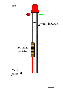
Test the probe by connecting it across your power supply. It should light connected one way, but not light when connected the other way around.
Now you can use the ends of the wires to probe the circuits for signals - the led will light (or flash) if it gets a signal (positive voltage). The longer lead of the diode goes to the circuit you want to probe (for a positive signal) the other lead (from the side of the LED case with the flat on it) goes to a good ground (such as the heat sink).
7) Check to see what (if any) functions work. Try the loopback test, the serial communications test, the clock count-up of the processor, and check for power and ground to the pins of the processor (see the assembly guide steps for details). Verify that no components are touching the crystal (Y1), which might prevent it from working properly.
8) Note which (if any) of the LEDs light on the Stimulator, and under what conditions. If your are able to isolate the problem to a particular area of the MegaSquirt® EFI Controller, check the schematics for that function, and double check all the related components for correct value, orientation, and proper soldering,
9) The most common cause of a MegaSquirt® failing after it has been working for a while is excessive flux residue. The flux residue can absorb water from the air and short MegaSquirt® internally. The solution is to clean the PCB with:
Also look carefully for any solder joints that may not be perfect. 'Cold solder joints' are joints that look okay, but have not bonded properly to the solder pad on the PCB. Cold solder joints often look grey or powdery after a while. These will often work okay at room temperatures, but not when hotter or colder. If you have any doubt, reflow the solder joints with a hot soldering iron (hold the hot soldering iron against the joint until the solder melts again and flows out over the solder pad.
10) The LEDs flash briefly when MegaSquirt® is powered up with the bootloader jumper in place. However, they also flash and go out if no rpm signal is received. The Warm-Up and Accel LEDs do not light continuously, even if the conditions for them are appropriate, until an rpm signal is received. So this will make it look like no code has been loaded. If you suspect problems with the stimulator (for example, everything seems to work, but there is no RPM indication in MegaTune) follow these steps for a V2 stim (V2.1 instructions pending):
For the VR sensor:
|
OR (Do NOT install both sets of
jumpers, chose one set or the other!) |
For the Hall sensor, optical sensor, or
points:
|
With a VR sensor on the VR input circuit: Start with the R56 pot all the way counter-clockwise, and R52 about 6 to 8 turns clockwise from the fully counter clockwise position. The fully counter clockwise position is reached when the pot clicks (you can feel and might be able to hear this). The pots are 25 turns from the fully clockwise position to fully counter-clockwise position.
With a Hall sensor (or other square wave input, like an EDIS or HEI, or on the stim) on the VR input circuit: Start with the R56 pot about 6 to 8 turns clockwise from the fully counter clockwise position, and R52 about 6 to 8 turns clockwise from the fully counter clockwise position.
11) If everything seems to work in MegaTune, including the RPM, but the injector LEDs don't light, the most likely problems people have is either the LEDs are in backwards, or the PWM% is set to near zero.
Note: If you have a MS-II™ controller with version 2.88+ code, and on the stim the INJ1 LED is always on, but the INJ2 LED is flashing normally, and you are running V2.88 firmware, make sure you have ECU type set to MegaSquirt-II (=1) instead of MicroSquirt® (=2). Then cycle the power to MegaSquirt (i.e., turn the power off, then on). This should fix that particular issue.
If these are okay, then you need to check that the FET driver (U4) is receiving signals from the CPU. Then you need to check that the FET driver is sending the proper signals to the FETs. Then you need to check that the FETs ground the pins properly, so that the LEDs are getting the correct signal.
To do this, build an LED tester as shown above (step #6). Set the stimulator's RPM pots to indicate about 1500 RPM on MegaTune. Put the ground end of the tester in the boot header hole nearest H1, furthest from the CPU.
If the output pins are flashing, then you have a problem with either the DB37, or the stimulator itself. Recheck the LED orientation, and the soldering of the DB37 connectors, and the stim LEDs (D2, D3) and stim resistors (R5, R6).
12) If you have trouble with the Throttle Position Sensor reading in MegaTune, the problem is most likely with the wiring at the TPS. Refer to the TPS section of the wiring guide for more information.
However, if it also gives problems on the stim, you need to look at the following components to make sure they are correct: C8 (0.001), C9 (0.22), and R9 (1K Ohm). Check all the solder joints as well. Also, make sure there is no excess flux around the affected components. If all of these are okay, you need to look a bit deeper.
Disconnect the stimulator and remove the 68HC908 processor. The TPS signal connects to pin 26 of the CPU, so you might check that this pins is soldered properly. You can measure the resistance of R9 directly on the board (it should be about 1K Ohm ± 50 ohms). R9 is above the "&" in the copyright notice. You can also check the resistance from the CPU pin #26 (near the H1 boot header) to R9 - on the side of R9 nearest the DB37 you should have less than 1.0 ohm (0.1 is better), - on the side of R9 nearest the DB9 you should have ~1K Ohm.
13) If you are having trouble getting values to 'stick' in your MegaSquirt® EFI Controller, check your power supply. Typically, a bad power supply will allow you to set values, but they will revert to the previous values after powering down. PC power supplies are especially notorious for this, and should be avoided.
14) a. If your MegaSquirt® starts up fine, then fades and dies, the issue may be C22. On the stim, MegaSquirt® might die after a few seconds, in the car the engine might start and run for several minutes (or seconds, or not at all). Using a wall-wart adapter instead of a 9 Volt battery might help on the stim, but possibly not completely.
By far the most likely cause of C22 giving problems is it being in backwards. C22 is a polarized cap, meaning it has to go is a certain way (the positive lead should be furthest from the heat sink). It is a small cap, with an even smaller "+" symbol imprinted on it, and it is easy to get it in the wrong way. C22 is used on the Vref output circuit. If C22 is failing, it might not conduct when cold, but when warmed up it could short the 5 Volt supply to ground, and MegaSquirt® will not run. (Note that on the stim a dying 9 Volt battery can give similar symptoms, so check that first. Also, if you do not find the problem in the step above, check your soldering as described in step #4.)
14) b. One the other hand, if the MegaSquirt® won't respond at first (when cold), or won't start with a serial cable and laptop attached, but works normally after a few seconds of powering up (or a few cranking tries), then suspect D19. On a V3 board D19 protects the 5 Vref from voltage spikes. The supply is 5 Volts, so the Zener diode rating must be higher than that, otherwise the diode will conduct all the time and fail quickly from excessive heat/current. In theory, 5.1 Volts is okay. However, in practice, these diodes typically have a tolerance of ~10%, meaning that a 5.1V Zener diode may conduct at 4.6V, and thus conduct all the time, heat up, and fail. A 5.6V can be as low a 5.1 Volts, which is fine. Also, these diodes have a temperature dependence - their rating when cold is lower than when hot (actually Zener diodes greater than 5.00 volts act this way, diodes rated less than 5.00 volts have a higher rating when cold). So you should replace D19, and moving up to a 6.2 Volt Zener diode, such as DigiKey 1N4735ADICT-ND would be a good idea (it provides slightly less protection, but potentially much better reliability).
However, note that in some cases the symptoms of C22 or D19 failing can mimic each other, so you should check both if you have problems getting consistent power (and check the stim battery/power supply if using a stim).
Also, if the MegaSquirt is slow to start up, you might check that you haven't accidentally shorted the 5 Volt supply (by mis-wiring the TPS sensor, for example). A voltmeter on the regulator should show a steady 5.00 Volts (± 0.10V) between the regulator pin furthest from the DB9 and the center pin of the regulator, and the external 5Vref supply (DB37 pin 26) should show a constant 5.00 Volts (± 0.10V) within a few milliseconds on start-up and at all other times MegaSquirt is powered.
15) If you serial connection doesn't work (or has stopped working), and you have tried the tips here: connection troubleshooting guide, you need to do some hardware troubleshooting. On a V3 main board, the following should be connected:
You should check that you have 5.0 Volts (±0.10) on the MAX232 pin 16, and ground on pin 15. Use the middle pin of the voltage regulator as a ground for measuring the voltage, and check that you have less than 1 Ohms resistance between pin 15 and the center lead of the voltage regulator.
If you have your MAX232 in a socket, make sure the MAX232 is well seated in the socket.
The associated components for the MAX 232 are (on a V3 main board): C26, C27, C28, C29. Make sure they are the right components, and are well soldered and not bridged.
If all of the above are okay, replace the MAX232 (cut the legs, then remove the body of the IC, and unsolder the legs one at a time to avoid damaging the PCB). The MAX232 does not tend not to 'wear out', so the amount of use isn't important, but they can fail after a few hours if they have seen a static shock at any point.
16) If you have MAP sensor spikes that aren't traceable to back-fires, etc, and you are using PWM to limit the current to low impedance injectors, you might have to modify flyback circuit. The fix for this specific problem (noise in the sensor signals, and a noisy +12v battery signal, spikes to 17v, dips to 7v) was to decouple the flyback +12v lines (both TIP125's) from the MS +12v input pin, and run them back to before a noise filter on the +12v input of the MegaSquirt.
To do this, lift the +12v pin of each of the TIP125's in the flyback circuit. The TIP125 are Q9 and Q12 (the ones with the mica insulators). The 12V pin on the TIP 125 is the pin in the middle - melt the solder and pull the pin up with needle nose pliers. Then run a wire from each of the pins you pulled up independently back to the raw +12v supply (outside of the box), and before the noise filter. You can ran the wires through the spares (SPR3 and SPR4, which go to DB37 #5 and #6). 20 gauge wire is fine.
Here is a little explanation on the flyback during PWM.
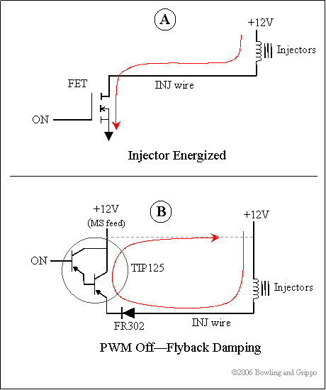
The top drawing A shows the current when the injector driver is on, during the high-time of the PWM waveform. Basically the FET is turned on, energizing the injector. This is the PWM high time, and it depends on the setting of the PWM duty cycle.
The second drawing B is the path when the driver is turned off during PWM flyback damping, or recirculation mode. This occurs during the off time of the PWM current limit. During this time the injector is trying to maintain the current that was there during the PWM on time (google "Lenz law"). So the injector will generate a current (from the collapsing magnetic field) that flows thru the FR302 diode, the TIP125 transistor, thru the +12V feed and back to the injector. The +12V feed to the MS is used as a path. Note that this is the closed loop path, this is not ground-referenced - the +12V is used as a return path, not as the potential source.
Now if the +12V line has resistance, then this current path will cause a voltage drop across the line - Ohm's law. If you have ever used one of those portable lights on the long extension cord with the built-in socket (trouble-light) and ever ran a tool from this outlet, you may notice that the light bulb dims down whenever the tool is active. This is due to the resistance in the extension cord wiring, and by drawing more current the wire drops some of the available voltage, and this is seen in the light. More current means more voltage drop for a given resistance. Now if the extension cord is a large-gauge wire then the voltage drop is less.
Same thing applies here in the +12V line. Depending on the path of the current thru the +12V wiring from the raw +12V MS feed back to the injector +12V feed there are many places where could be potential voltage drops. Things like small-gauge wire, resistance in contacts like relays and MS connector, etc. can all add up.
You can also use the separate +12V lead just for the flyback. The flyback damp +12V is on the bottom of the PCB. This trace could be cut and ran thru a spare connector output. Best bet would be to run this wire direct to the injector +12V source in order to complete the damping circuit and to separate this from the MS +12V source.
There is more on this and fixing other noise issues here: Noise and MegaSquirt
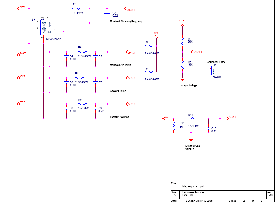
17) If your temperature indications in the tuning software are always stuck at 180°F (or 170°F), you either have a short-circuit or open-circuit to your sensor. The code is set to indicate 180°F when that happens (some code versions default to 170°F). If you have a stim, check your board out on that - if the tuning software temperature(s) moves with the pots(s), then the problem is in the wiring harness, and you will have to look very carefully at that. If it still doesn't work even on the stim, check the main board components shown for MAT or CLT in this diagram:
Note that you can check what the processor sees for voltage on the temperature circuits at the header that connects MS-II to the 40-pin socket (or directly on the processor pin for MS-I):
Be careful not to short the adjacent pins. These pins should change voltage when the sensor (or stim pot) changes resistance.
18) If you are having trouble with sensors, see: the sensor troubleshooting guide
19) Finally, if none of this helps to discover and solve your problem, send a message (including any information you found from doing any of the above) to the MegaSquirt Forums. Feel free to ask for help, that is why the MegaSquirt forums are there - just realize that you may be sent back for more information. You will solve your problem much faster if you provide as much detail as possible when asking questions the first time around. And, following the assembly steps, you will discover problems and correct them as you go along.
If all else fails, you can have someone else troubleshoot and repair your MegaSquirt. Peter Florance, who runs an electronics repair business, and who is a very active and informed member of the MegaSquirt® community, has offered to troubleshoot and repair MegaSquirt®s for those in need. The fee is based on standard shop rates, with a ½ hour minimum.
You can contact Peter at: peter@firstfives.org.