
The MSD 6A ignition is a popular aftermarket capacitive discharge, multiple spark ignition controller.
There were a number of different kinds of MSD 6A modules:
| Model | Part Number | Typical Applications | Features |
| MSD 6A | 6200 | Street/Strip | 4, 6, 8 cylinders even fire only |
| MSD 6A | 6246 | Street/Strip | odd-fire V6 |
| MSD 6AL | 6420 | Circle track and endurance racing | Rev limiter connections; 4, 6, 8 cylinders even fire only |

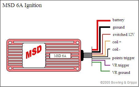
With a MSD modules, the ignition module wires you need to know about are:
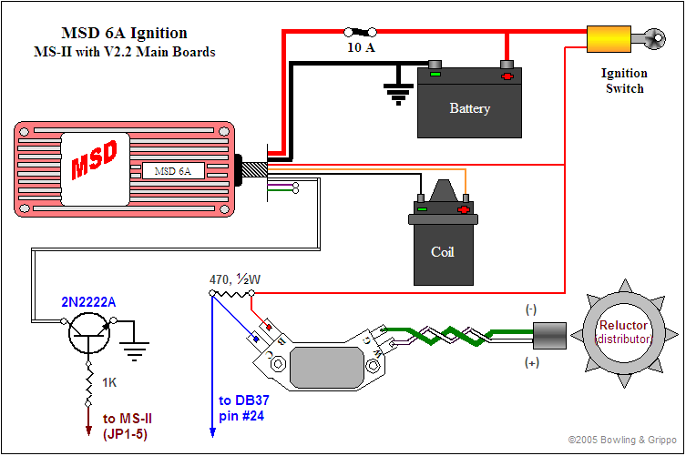
With the MSD ignition box, we do not use the VR sensor wires (orange and violet). Do not connect these. Instead, we send the signal from the Hall, VR, optical or points to the MegaSquirt-II box, then send the MSD ignition box a square wave signal on its white wire. To connect the distributor and MSD module to MegaSquirt-II, follow these steps:

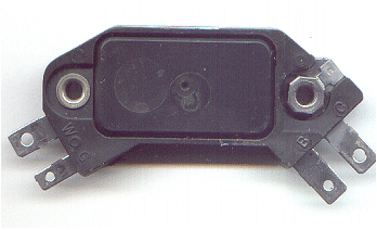
NAPA OnLine sells the 4-pin HEI ignition module, ECHTP45, for ~$39 + shipping. These are also widely available as Wells DR100, Niehoff DR400, Standard part numberLX-301 (~$28); or AC DELCO D1906 (~$33), and were used on many non-computer GM V-8s, V-6s and I-6s from 1975 to the mid 1980s.
Here is how to wire it up. The four HEI module terminals are labeled W, G, B and C.
W and G; hook up to the VR sensor. Hook a 470 Ohm, 1/2 watt resistor between terminal B and C. Hook terminal B to a switched +12V supply. Hook C to the tach lead on the MegaSquirt® box (DB37 pin #24). Be sure to mount the HEI module such that the metal bottom is connected to ground (either engine or chassis). The module will not get hot, since there is not much load (the resistor), but the metal still needs to be grounded.

In MegaSquirt® EFI Controller, be sure to install the Wing diode and the Ed capacitor, omit the Dave capacitor, and jumper the John Zener:
| PCB | Wing diode install | John Zener jumper | Ed Cap install | Dave Cap do not install |
| 2.2 | D5 | D8 | C12 | not used |
| 3.0 | D1 | D2 | C12 | C30 |
OR

Settings for the MSD 6A Module
When using the MSD 6A ignition modules, set the ignition parameters in TunerStudio to:
Parameter | Value |
| Ignition Input Capture |
|
| Cranking trigger | Trigger Rise |
| Coil Charging Scheme | Standard Coil Charge |
| Spark Output | Going Low (Normal) ('Going Low (Normal)' for MicroSquirt) |
| Maximum Spark Duration | 25.5 |
Under the dwell settings:
Parameter | Value |
| Maximum Dwell Duration | 25.5 |
To set the dwell to 25.5, you'll have to change the mainController.ini file for TunerStudio. This is in your 'C:\Users\..user..\Documents\TunerStudioProjects\..project..\projectCfg' folder.
Edit the following line with Notepad.exe (installed on most Windows systems, look under 'Start/All Programs/Accessories') or a similar text editor:
to
You must also set the initial position of the trigger (called the 'trigger offset'), then check it using the Trigger Wizard in the tuning software.
The 'trigger offset' in the tuning software is the number of degrees before TDC at which the VR sensor output goes from positive to negative, and the falling edge of the square wave is sent from the 4-pin HEI module to MegaSquirt-II™. This tells MegaSquirt-II™ where the crankshaft is positioned so that timing advance can be calculated appropriately. (Note that since the optoisolator (U4) inverts the trigger signal, you specify 'Rising edge' for the 'Input Capture' in the tuning software, which refers to the signal at the processor.) Positive trigger offsets are used to specify the number of degrees before top dead center (BTDC), negative numbers are used for triggers that occur after top dead center (ATDC).
Reference (tach) pulses come into MegaSquirt-II™ from pin R at 10° BTDC (this offset can be calibrated using TunerStudio so that the spark table values match the actual advance). At each reference pulse, the period between it and the previous reference pulse is calculated. The difference is used (with a time interpolation technique) to set up the timing pulse for the next ignition event. Specifically, the reference period is added to the time of the current pulse, a calculated amount subtracted for the advance, another amount subtracted for the dwell to determine the rise time.
The output signal from MegaSquirt-II™ (from the 5th hole of JP1 on the V2.2 MegaSquirt® PCB, DB37 pin #36 on the V3 main board) is used by the module to control the current through the coil. When the signal is pulled low, current stops, the magnetic field in the coil collapses, and a spark is produced. However, the low to high transition is not used to determine when coil charging begins, instead the MSD box controls this itself. Thus, the HEI module fires on the 'trailing edge' of the advance signal. The advance signal is generated by MegaSquirt-II from the tach signal by modifying the end point of the 'high' pulse.
If you are using a VR pick-up in your distributor and a 4-pin module, be sure to get the variable reluctor pick-up wires connected properly. Reversing the variable reluctor sensor wires and thus the polarity of the sensor causes the leading voltage to go negative first and the electronics ignores the positive going transition. Thus the trigger signal, if ever recognized, is the falling edge of the voltage as the end of the tooth passes, which is incorrect.
If you do not know which is positive and which is negative, you can check it with a timing light. Rotate the motor over until it is at some fixed figure, say 5° BTDC. Loosen the clamp and rotate the distributor until the armature vane is lined up with the center pole of the magnetic pickup. Set both the Base Timing and Initial Advance on MegaSquirt-II to 5°. Fire up the motor and check the timing with the timing light, it should be pretty close to 5°. If it is not close to 5°, then reverse the pickup leads and check it again.