The is an introduction to tuning with a programmable electronic fuel injection ECU. It is written specifically for MegaSquirt® or MegaSquirt-II™ EFI users who are new to tuning engine with a programmable controller, and tries to make very few assumptions about what you already know. Read this document before reading the applicable tuning section for those controllers, which are here:
This introduction to tuning has the following sections:
How an Internal Combustion Spark-Ignition Engine Works
Internal combustion engines are called that because the fuel is burned inside the working part of the engine (the cylinder) as opposed to the fuel being burned remotely (as in a steam engine, for example). Jet engines are internal combustion engines, but unlike automotive engines, they are not spark-ignition (they are continuously ignited by already burning fuel). The discussion here is limited to internal combustion, spark ignition engines. We begin by explaining how a 4-stroke cycle engine works (by far the most common type of automotive engine).
An engine has three primary 'control parameters' that we can manipulate to optimize the way the engine runs under various conditions:
An engine has one or more cylinders (if it isn't a rotary engine, etc.). These cylinders have a moveable piston in them. The piston seals the lower end of the cylinder, and because it is connected to a rotating crankshaft by a connecting rod, it moves from the bottom of the cylinder to the top (and back, repeating endlessly).
For the engine to operate, it has 4 cycles, each of which take one-half a crankshaft revolution, which is one 'stroke' up or down the cylinder. The strokes are:
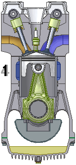 |
1. Intake stroke: draws air and fuel from the intake manifold, past the open intake valve, and into the cylinder.
The amount of fuel going into the engine must be based on the amount of air going into the engine so the mixture is appropriate for the conditions. The process of figuring out that appropriate amount of fuel (and spark) is called 'tuning'. When we have finished the tuning process, the fuel injectors always mix the correct amount of fuel into the air in the intake manifold, before the air/fuel mix enters the cylinders. |
| 2. Compression stroke: The intake valve closes (the exhaust valve was already closed), and the upward motion of the piston compresses the fuel/air mixture from atmospheric pressure to approximately 150 psi (the fuel burns better when it is compressed, and the theoretical efficiency of an internal compression engine is linked to its compression ratio). The pressure reached depends on the mechanical compression ratio, as well as the cam timing, throttle opening, and some other factors. BTW, this is the pressure you are checking when you do a 'compression check' with a pressure gauge in a spark plug hole while cranking the engine. | |
← Spark* →
| |
| 3. Power stroke: The air fuel mixture burns from the spark plug outwards within the combustion chamber while the piston is near the top of its travel. The burning fuel raises the temperature, and thus the pressure within the cylinder. The pressure pushes equally on all the surfaces of the combustion chamber, cylinder and piston, but because only the pistons can move, this is where the work is done. The hot gases push down on the piston, forcing the crank shaft to turn. | |
| 4. Exhaust stroke: At the bottom of the power stroke, the exhaust valve opens and the subsequent upwards motion of the piston (aided initially by the residual pressure in the hot exhaust gas) pushes the exhaust gas into the exhaust system. The exhaust valve closes near the top of the exhaust stroke. |
* - not a stroke, but a very important part of the process nonetheless!
and these are repeated endlessly for each cylinder as long as the engine is running.
Note that the piston is only making power on one of the four strokes. What makes the crankshaft rotate to perform the other three strokes? There are two answers:
Before reading further, you should review the glossary of basic tuning terms at the end of this document. You can also click the underlined terms in this document to go to the definition of that term.
At the top of the cylinder is the combustion chamber with the intake and exhaust valves. There are one or more intake valves and one or more exhaust valves (the most common combinations are one intake and one exhaust valve, or two intake and two exhaust valves - a four-valve engine - often referred to as a 16-Valve engine on a 4 cylinder, because of the total number of valves). The valves open and close in precise coordination (via a camshaft and 'valve train') with the piston to allow the air/fuel mixture to be drawn into the cylinder, and the spent exhaust gases to be removed.
The cam shaft has 'lobes' on it. These have raised areas that open the valves when the rotate into position. Since we want the vales to open once per 4-stroke cycle (which is two revolutions). Not surprisingly, the intake valve(s) is open on the intake stroke, and the exhaust valve(s) is open on the exhaust stroke. The valves are closed on the compression and power strokes.
There is one 'lump' on each lobe per cam, so we want the cam to rotate at exactly ½ the crankshaft speed (which will result in the valves opening once every two revolutions of the crankshaft). We do this with gears. The gear on the cam has twice as many teeth as the gear on the crank, and the cam moves ½ as fast. The gears may mesh directly, or may be linked by a chain or belt. Any of these are fine, the important thing is that the cam has twice as many teeth, and so it rotates one-half as fast.
The exact timing of the valve openings and closings, and the lift, is quite technical. It does have a major effect on the engine's efficiency and power output, but a discussion of cam timing is beyond the scope of this article.
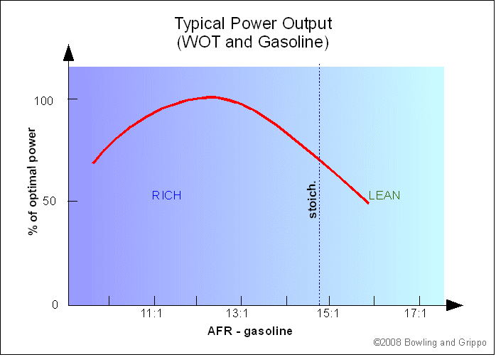
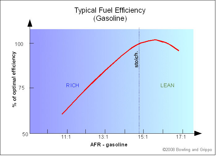
The amount of air going into the engine is primarily determined by the throttle (as well as any limitations based on the port and valve design, cam timing, etc.). The throttle can be opened anywhere from 0% to 100%. Larger openings mean more air going into the engine in general, and more power output from the engine. The fuel must be in a narrow range in proportion to the air. The exact ratio varies. The chemically correct ratio is called 'stoichiometric'. More fuel is 'rich', less fuel is 'lean'. Stoichiometric mixtures are around 14.7:1 for gasoline (by mass)
What is 'Stoichiometric'?Octane, the most 'representative molecule' in gasoline, burns as:
C8H18 is the formula for octane. The oxygen (O2) is consumed from the intake air. Nitrogen (N2) is also present in the atmospheric air, but ideally does not participate in any reactions (it is quite inert at low temperatures). Note that the combustion products are carbon dioxide (CO2) and water (H2O), if the combustion is 'perfect'. Also, note that there are the same number of each kind of atom on each side of the chemical equation: 8 carbon, 18 hydrogen, 25 oxygen atoms on each side, so the equation is properly 'balanced'. In practice, premium gasoline has a ratio of 8 carbon atoms to 15.4 hydrogen atoms in its composition on average (and historically very few other atoms). The higher carbon ratio is because of branches, double bonds, and rings that allow for fewer hydrogen atoms per carbon atoms. This means that gasoline will burn a bit richer than pure octane. A greatly simplified chemical analysis for perfect gasoline/air combustion (the ratio of fuel to air required for perfect combustion is known as stoichiometric - pronounced 'stow-eék-kee-o-metric') is:
Note that there is no such thing as C8H15.4, but you can think of it as an average of various hydrocarbons, such as 65% C8H14 + 35% C8H18, or a number of combinations that result in a carbon:hydrogen ratio of 8:15.4. Also, the coefficients above represent ratios of the number of molecules. If you want a 'correct' chemical equation in terms of molecules, multiply the coefficients by 20 (I.e. 11.85×20 = 237, 8×20 = 160, 7.7×20 = 154, etc.). The 11.85:1 ratio of oxygen molecules to gasoline molecules is the ratio of their numbers, not their masses. To get the mass AFR, we need to calculate how much each molecule weighs. Carbon (C) has an atomic mass of 12.01 daltons (the unit of atomic mass), oxygen (O) is 16.00, and hydrogen (H) is 1.008. For the traditional blend of hydrocarbons in gasoline (not including all the modern additives and oxygenates), the average molecular mass is:
8 × 12.01 + 15.4 × 1.008 = 111.6 daltons
(Modern 'reformulated' gasoline is closer to 108 daltons, with a carbon:hydrogen ratio of 7.75:14.8. The result is the same stoich AFR.) The mass of the oxygen molecule (O2) is:
2 × 16.00 = 32.00 daltons
So the mass ratio of O2:gasoline is 11.85 × 32.00 ÷ 111.6 = 3.40:1 This is the correct mass ratio of oxygen to gasoline. However, the engine doesn't breath pure oxygen, it breathes air. Dry air is only 20.95% oxygen (O2) by volume and 78.08% nitrogen (N2). Since nitrogen has an atomic mass of 14.01, and air has ~1% argon (39.95) and other trace gases, air is thus:
The mass percentage of oxygen in dry air is higher than the volume percentage because the oxygen molecule is heavier than the nitrogen molecules, etc. for a given volume (or number of molecules). And therefore the stoichiometric mass ratio of air to gasoline is:
For 'imperfect combustion' of gasoline see: Tuning and Emissions Note that we have not considered the 1% to 4% of the air that is water vapor near ground level (depending on the local weather), and this is an important factor in 'fine tuning' on very high specific output engines. As well, different formulations of gasoline have different stoich. ratios, especially if they are 'oxygenated blends' (mixed with molecules containing oxygen, such as alcohols). Other fuels have different stoichiometric ratios:
Here is a calculator for determining the stoichiometric AFR for various carbon based fuels (of the form CαHβOδNγ):
|
Stoichiometric air/fuel ratios are not necessarily the optimal target for best power or economy though. For best power, you will want to run rich, for best economy you will want to run lean of stoich:
There is more on this below.
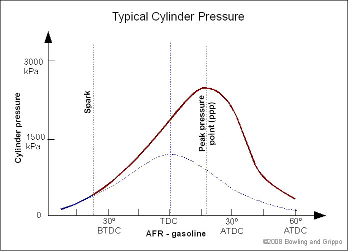
Advance refers to the precise crankshaft position where the ignition is initiated by a spark from the spark plug. It is always referenced to the crankshaft position in degrees (the symbol for degrees is °, the same as temperature). Since there are 360° in a crankshaft revolution (or any complete circle), one intake stroke, which takes ½ a revolution, is 180°. Normally the advance is specified as 'before top dead center' (BTDC). This means the number of degrees the crankshaft would have to turn to reach the very top of it travel from the spark point.
Sparking before TDC is necessary because the fuel and air take some milliseconds to burn. Typical values range from 5 degrees BTDC at idle to 35 degrees at wide open throttle (WOT) and possibly even higher under cruise conditions. The flame front moves at about 50 mph (~73 feet/second or ~880 inches per second) at high cylinder pressures and appropriate AFRs. The pistons can travel a considerable distance in the time it takes for the fuel to burn all the way from the spark plug to the most distant regions the cylinder. For example, at 880 in./sec and a 3.5" bore, if the spark was centrally located, the burn would take 1.75/880 = 2.0 milliseconds.
If the burning takes 2 milliseconds to reach maximum pressure, at 3000 rpm the piston & crank will travel 36° in that time. There is an optimal point (peak pressure position - ppp) in the piston movement when we want the burning gases to reach their peak pressure (usually about 17° ADTC), so we need to start the burn early to get the peak pressure where we want it (in this case 36°-17° = 19° BTDC).
With a larger bore and a non-centrally located spark plug (typical of 2-valve engines), more advance is needed. For example, on a 4.00" bore, with a spark plug 1.3" from one side (and 2.7" from the other), the burn time rises to: 2.7/880 = 3.1 milliseconds. In this time, the piston/crank travels about 55°. So under the same conditions as above, the timing needs to be increased to: 55°-17° = 38° BTDC!
Timing advance is low at low engine speeds, because the piston is moving slowly, and the fuel has time to burn near TDC. At higher speeds, the timing must be advance. At some point (usually about 3000 rpm), the combustion turbulence ensures a quick burn, and no further advance is necessary. The details of how optimal spark advance is affect by various factors would fill a large volume, and include relevant topics like bore size and chamber shape, mixture swirl and tumble, and a myriad of other things...
Too much advance isn't good though. The peak pressure is reached too early, and the result can be that the burn doesn't proceed smoothly across the combustion chamber, but instead fuel and air in the furthest areas of the chamber spontaneously ignite from the pressure and radiant heat in the chamber (this is called 'detonation' and it can be very destructive).
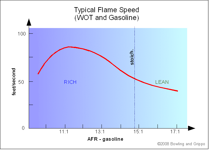
As well, spark and fuel tuning interact. That is, the amount of fuel affects the optimal timing, and vice versa. Here is a graph showing the relationship on one typical gasoline engine:
In addition to being timed right, the spark itself must be of sufficient voltage to jump the spark plug gap, and have enough energy to sustain the spark long enough to initiate combustion. There is more information on that here: www.megamanual.com/seq/coils.htm#gap
The force of the piston(s) on the crankshaft (through the connecting rod) becomes a rotational force called 'torque', and is measured in ft·lbs. Work is done when force is exerted over a distance (measured in lb·ft) such as lifting 100 pounds 330 feet. Power is the rate at which work can be done (lifting 100 pounds 330 feet in 60 seconds, for example).
The rate at which the engine can produce torque is a function of rpm, and is called 'horsepower ' (HP). In particular, horsepower is defined as the ability to do 33000 lb·ft of work in one minute (ex. 1 horsepower can raise 330 pounds 100 feet in a minute, or 33 pounds 1000 feet in one minute, or 1000 pounds 33 feet in one minute, etc.).
For a rotating engine crankshaft, the torque tells us the force at a radius of 1 foot. In one revolution, that force will be exerted over the circumference of a 1 foot circle, so a force of F = torque÷r, over a distance of D = 2πr, where r = 1 (but note that the r in both equations cancel each other out when we calculate the work done: W = F × D).
The result is that the work (W) done per revolution is 2π × torque. This work is done rpm times per minute. So the functional relationship for horsepower is:
| horsepower (HP) = | 2π × torque × rpm | = | |
33000 | 5252 |
Here is a calculator to determine HP from torque (at a given rpm), and vice-versa. Enter a number in any field, then click outside the text box.
One effect of this relationship is that the same torque at a higher rpm makes more horsepower (which is why 2.4 liter F1 engines with just 200 lb·ft of torque - less than many passenger cars - can make over 700 HP at their 19000 rpm maximum speed). And it is horsepower that makes the vehicle accelerate. Also, note that HP = torque at 5252 rpm (so take any dyno results where that isn't true with a big grain of salt).
The tradeoff is that engines run best only over a certain limited rev range. A stock engine might produce useful power over a range from 1500 rpm to 5500 rpm, while a race engine might make power from 5500 to 9500 rpm because of its cam timing, compression ratio, intake/exhaust design, etc. The stock engine would break if it was rev'd like a race engine, the race engine would have no power off idle for cruising around town (and would have poor fuel economy, high emissions, suspect reliability, etc.).
You may hear people talk about street engines needing torque for best performance, race engines needing horsepower. What they mean is that street engines need to be built for lower rpm, race engine for high rpm. Both cases would like to have as much horsepower as possible, *and* as much torque. But on the street, you don't want to have to downshift twice and rev to 5500 rpm every time you want maximum power (such as at a stop light).
The tuning process starts with setting the general parameters to get the engine started, and continues until the engine performs optimally under all conditions (as judged by the tuner). To optimize the engine performance (including power, efficiency, cold start performance, etc., etc.) we start with base settings, and adjust them one at a time to get the best performance. We will cover only the optimization/adjustment process here, the settings are in other documents, and are vehicle specific.
There are a few fundamental principles to tuning:
The tuning process is an iterative process of determining what the engine wants. We:
Note that after setting one or more parameters, you may have to go back and re-set other that you have already done (i.e., 'iterate'). This is because many parameters 'interact'. For example, If you set your accel enrichments to be optimal, then set your VE table to be optimal after that, the accel enrichments may no longer be right. If the VE table was originally rich, the accel enrichments didn't need to be as large, so leaning the VE table has now exposed the fact that the accel enrichments are too small - so you need to retune them. Conversely, if the VE table was too lean, and you fixed it by richening it appropriately, the accel enrichments may be too large and you may need to reduce them.
General Settings and Engine Parameters
We have three general sets of parameters to set:
These could be further divided into tuning adjustment parameters (that we use for tuning) and configuration parameters (that we use to set up the ECU and that are constant for a given engine/vehicle). For example, req_fuel is a configuration parameter - it tells the ECU how big the engine is and how much the injectors can flow, etc. We don't use it (normally) to change the fuel delivered once we have calculated it for our engine and its fuel system. On the other hand, VE is a tuning adjustment parameter - we use it to control the fuel amount. In this document, we'll only cover tuning adjustments. Set-up advice can be found in the appropriate document, such as: www.megamanual.com/ms2/configure.htm
Also, parameters may appear as single value, 2 point values, or tables.
One important thing to note is that these parameters typically come as milliseconds or percentages.
Numbers that are in milliseconds (like the accel enrichments, etc.) richen the mixture when they are increased, and lean it when then are decreased.
In MegaSquirt® controllers PWM percentages are also 'absolute'. This is for both injector current limiting and PWM idle valve control. These can only run from 0% to 100%.
Finally, some parameters are 'multipliers' (in %) like the warm-up enrichments. They are like the 'absolute' percentages, but they can be (and often are) larger than 100%. What these do is take the base pulse width obtained from the req_fuel, VE, and MAP, etc., and multiply by the parameter value. So a warm-up enrichment of 100% means no change, while a value of 130% means increase the fuelling by 30% over what was calculated from the MAP, VE, etc. 90% would mean decrease the fuelling by 10% (such as in the decel fuel amount). VE percentages are tell MegaSquirt how much air is entering the cylinder, and it tries to match the air with the right amount of fuel. If the VE is increased in the VE table, then the fuel is increased to match. So when you want to richen the fuel at a particular rpm and load, you increase the VE table entry(s) at that point. Conversely, if it is already too rich, you decrease the entries.
Operating Envelope and Specific Conditions
There are a number of general operating conditions that apply to most automotive applications. We list some below, with some tuning considerations for spark, fuel, and air (and the relevant parameters):
Tuning Factors→ Operating Condition↓ |
Target Fuel AFR |
Ignition Advance |
Primary EFI Control Parameters |
Other Notes/Links |
||
Fuel (& carb equivalent) |
Spark (& distributor equivalent) |
Air (& carb equivalent) |
||||
| Cranking | Very Rich | Low advance (minimize kick-back) | Cranking pulse widths, (choke) |
Trigger Offset, Trigger Rise (none) |
IAC cranking position, Crank-to-run taper | Cranking Pulse Widths, Getting the Engine Started and Idling, Tuning the Spark Table |
| Warm-Up | Rich | Advance slightly | Warm-up enrichment (WUE), Afterstart enrichment (ASE) (choke) |
Cold Advance table, (none) |
IAC Idle Steps, (fast idle stop) |
Tuning the Cold Start and Warm-Up |
| Idle | Might need to be rich or lean, depending on many factors | Depends on emissions requirements, typically 5° BTDC to 15° BTDC |
VE table (low rpm) (idle mixture screw) |
Spark Advance table (distributor rotation) |
Throttle stop, (choke) |
Tuning the Idle Control, Tuning the Spark Table |
| Cruise | Lean (14.8:1 to 16+:1) | High advance | VE table (low kPa), (main jet) |
Spark Advance table, (vacuum advance) |
n/a | Tuning for Economy, Tuning the Spark Table |
| Minimum Emissions | Stoichiometric | Moderate advance (slightly retarded) | VE table (main jet) |
Spark Advance table, (vacuum, mechanical advance, retard canister) |
Deterine by testing | Tuning and Emissions Tuning the Spark Table |
| Acceleration | Rich | Advance increasing up to ~2500 to 3500 rpm | Accel enrichments: TPSdot, MAPdot, X-Tau, (accelerator pump/nozzle) |
Spark Advance table, (mechanical advance) |
n/a | Setting the accel. enrichments, X-Tau Enrichment |
| WOT (wide open throttle) | Rich (12:1 to 13:1) | Advance depends on fuel, combustion characteristics, etc. | VE table, (main jet, power valve) |
Spark Advance table, (mechanical advance) |
n/a | Tuning the VE Table, Tuning the AFR Table, Tuning the Spark Table |
| Deceleration | Lean | Increased advance | VE table (none) |
Spark Advance table (vacuum advance) |
n/a, (dashpot) |
Tuning the VE Table, Tuning the AFR Table, Tuning the Spark Table |
There are other potential conditions, of course, like tuning for elevation (barometric correction), tuning for heat soak (IAT corrections), and many others. The above are the conditions that everyone will likely need to do for a general use vehicle, though. Note that some of these conditions overlap - for example, you need to tune the idle when warming up (with things like the IAC steps, warm-up enrichments, etc.).
Summary of Tuning Symptoms and Remedies
In the table below you will find some common tuning symptoms, and the action you might take to reduce them:
| Remedy | Fuel | Spark |
| Need to reduce ↓ |
Too Rich:
|
Too Advanced:
|
| Just right |
|
|
| Need to increase ↑ |
Too Lean:
|
Too retarded:
|
Note that the above remedies apply only at the conditions (rpm, MAP kPa, coolant temperature, etc., depending on the parameters affected) where the symptoms appear. In order to tune, you must consider this very carefully, and organize your tuning efforts to only affect the regions where you have problems. We will discuss this in more detail below.
To adjust the amount of fuel to correct a lean condition, we increase the parameter value (whether it is in % or milliseconds). The parameter we want to increase may be in the VE table, the accel enrichments, the warm-up enrichments, the afterstart enrichments, or the cranking pulse widths (among others). Which parameter we adjust depends on the conditions under which we find the engine is lean. Conversely, if the engine is rich, we decrease the appropriate parameter(s). See: Summary of Tuning Symptoms and Remedies above.
For maximum power, we want to run richer than stoichiometric. This is because the engine's output is primarily limited by the amount of air that enters the cylinders. That, in turn, limits the amount of fuel we can burn. However, to make sure all of the oxygen is consumed, we must supply a richer than stoich. mixture, so that any residual oxygen always has fuel nearby to combust with. The result is that maximum power typically occurs between 12.5:1 and 13:1 (if the ratio is much richer than that, the excess fuel actually quenches the flame front).
It may also be true that the engine wants to idle rich of stoich., especially if it has an aftermarket camshaft. A 'hot street' engine may idle best at 13:1 to 14:1 (where it will achieve minimum MAP kPa, which should be the tuning goal for idle). However, for emissions regulated applications with a catalytic converter, the idle mixture is usually stoichiometric in order to maximize the conversion efficiency.
For one naturally aspirated engine, here is an example of a target AFR table:
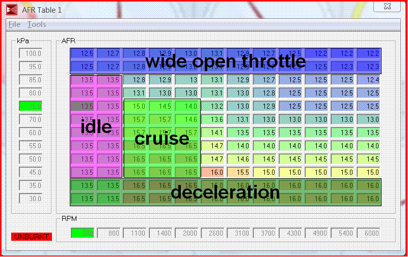
Typically, naturally aspirated engines want the mixture slightly learner at peak torque than at peak horsepower. So the 'WOT' row at 100 kPa is slightly leaner at lower rpms (except at the very lowest rpms, where the richer mix acts like additional accel enrichment - and also helps with cold starting performance).
If this engine was boosted (supercharged or turbocharged), the kPa scale would extend above 100 kPa, and the mixtures would become even richer, as rich as 10:1 at maximum boost in some cases (the rich mixture cools the piston, and also helps prevent detonation).
The area around 1100 to 2000 rpm and 45 to 75 kPa is this vehicle's 'cruise' (the low rpm is a result of a 4-speed overdrive transmission). Leaner mixtures here really help the fuel economy, and prevents the plugs from fouling. For this engine, 16.5:1 AFR is the leanest this engine/vehicle can run without a 'lean surge'. Note that in fully warmed up conditions, the cruise kPa on this vehicle is around 45 kPa, so the target AFR would be 16.5:1.
The area between 500 and 800 rpm below 85 kPa and above 45 kPa is idle. 13.5:1 gives the lowest MAP kPa, and thus the most efficient idle on this engine (though this AFR would not be suitable for an emissions controlled engine).
The rest of the table is 'conventional', with just some blending to avoid sharp transitions (which can definitely be felt in the car).
The same areas of the VE table are used for tuning to reach these target AFRs (in most cases, the AFR table is only used to set the wide band target, so if the EGO closed loop isn't operating, the fuel is controlled from the VE table). The spark table is very similar as well (though it can have its own bins, so the spacing might vary from a VE/AFR table even in the same engine).
There is more on tuning fuel here: Tuning Your MegaSquirt-II™ (or MicroSquirt®) Controller
The spark advance value that appears in MegaTune's spark table is the spark advance you should see at the crank with a timing light. It automatically includes any trigger offset you have entered (if you have calibrated it with the 'Trigger Wizard' in MegaTune). Spark advance can be set to tenths of a degree. To create and tune the spark advance table, you should try to understand what your engine needs in the following areas:
For example, most small block Chevrolet V8 engines like about 32° to 38° degrees total advance at wide open throttle (WOT), depending on the heads, compression ratio, and fuel used. Note that you are aiming to have the rpm based advance (analogous to centrifugal advance on an old style distributor) come in at the right rate relative to engine rpm. Typically, you want it "all in" by about 2800-3200 rpms for a street performance motor. Additional advance above this rpm point isn't needed because increased combustion chamber turbulence results in faster burn times. Note that getting the advance in sooner does NOT build peak HP, but it does build low rpm torque.
Note that the optimum amount of total advance is not necessarily the most that doesn't detonate. For example, with a modern cylinder head design, you might get maximum power at 32°, but might not experience any detonation until 38°-40°. However you will still want the advance to come in as quickly as possible (without knocking) up to 32°.
The exception to maximizing the total advance is the initial advance the engine uses when cranking. Higher initial advance will generate better 'off-idle' response (especially with an automatic transmission), but can cause hard starting, to the point of physically breaking the starter. Some sources recommend up to 14° to 20° of initial advance for performance engines. However, if you have installed MegaSquirt-II™ (or MicroSquirt®) on a high compression, large displacement engine that already puts an additional strain on the starter, limit your initial advance to 4°-12°, then have the advance come in rapidly after 600 to 800 rpm.
To tune the spark table, you will need drive the car and listen for detonation. If you hear any (or better yet, if a datalog shows any feedback from the knock sensor) reduce the advance at the spark advance table point where the detonation occurred. Start at low engine speeds and low engine loads, and work towards higher speeds/loads progressively. Always keep the spark table smooth by adjusting the neighboring 'cells', or driveability may suffer.
Let up on the throttle immediately if you hear the rattles of detonation. Then remove and inspect your spark plugs. Look for evidence of detonation on the porcelain nose of the spark plug that surrounds the center electrode. detonation will show as "salt and pepper", which is tiny flecks of carbon and/or aluminum that indicate detonation has occurred.
If there are no 'rattles', and no “salt and pepper”, you can increase the advance by a few degrees, and repeat. Check the spark plugs after each drive. As you continue to increase advance, you will eventually either hear detonation (let off the gas immediately!) or you will slow down. At this point, decrease the advance at that point of the spark advance table, increase the VE at the same point in the VE table, or use higher quality fuel. Do not continue to operate an engine that shows signs of detonation, even if it is brief.
There is more on tuning spark advance here: Making a Spark Advance Table and here: Tuning the Spark Table
Glossary of Some Basic Tuning Terms
Following are a few basic tuning terms used when tuning programmable EFI systems. These will help you to understand the above discussion, so you should read them carefully, and you should review these often while reading the manual.
AFR - refers to the ratio of air to fuel in the intake mixture going into the cylinder. It is always air mass:fuel mass ratio, and is typically between 11:1 and 17:1 (the volume ratio is closer to 9000:1 air:fuel.)
ATDC - used for ignition advance timing, it refers to the crankshaft position (in degrees) After Top Dead Center on the power stroke.
Boost - This refers to the artificial increase in manifold pressure above the barometric pressure based on some sort of mechanical compressor or pump. Typically this is a turbocharger (exhaust driven), or a centrifugal or Root supercharger (belt driven). boost can range from quite low levels (3 to 5 psi, or about 20 to 30 kPa) to very high boost (MegaSquirt's standard MAP sensor is limited to about 21 psi, or about 150 kPa above baro of boost).
BTDC - used for ignition advance timing, it refers to the crankshaft position (in degrees) Before Top Dead Center on the compression stroke. Most ignition timing events occur before top dead center, usually in a 5 BTDC to 40 BTDC range.
CLT - For MegaSquirt® EFI Controller, this refers to the coolant (antifreeze + water) temperature, and is an important factor in determining the warm-up and cranking enrichments.
Detonation - Normally, the burning (aka. 'combustion') starts at the spark plug and spread smoothly (but very quickly) from there. If the combustion starts in a second location within the combustion chamber, because of a hot spot in the cylinder, then the two 'flame fronts' each raise the pressure in the cylinder, possibly to destructive levels.
EGO - refer to exhaust gas oxygen. The amount of oxygen remaining in the exhaust can be a good indication of the air/fuel ratio of the intake mixture. There are a few types of EGO sensors that can directly measure this remaining oxygen. One type, a 'narrow band' sensor, measure only one mixture called stoichiometric (which is the chemically correct mixture for a 'perfect burn'). A second type is the 'wide band' sensor, which in conjunction with a controller board is capable of measuring deducing AFR ratios from 10:1 to 20:1 (in other words, all the ratios we are interested in).
EGT - refers to exhaust gas temperature. This is sometimes used for tuning,but it is difficult to generalize about it, and it is not often used in MegaSquirt® tuning. It can be useful if you have an idea of what is normal for your engine.
IAT - The refers to the intake air temperature, or the temperature of the air entering the cylinder. This is important because we if we know the temperature and pressure of a specific volume of gas, we can calculate the mass of that gas, and determine the amount of fuel we need to add. So we measure the IAT, the MAP, and then use the volumetric efficiency (VE) to estimate how much the corresponding values will be in the cylinder. The relationship between the pressure, temperature and volume of a gas (air, in our case) is called the 'Ideal Gas Law'. MegaSquirt® uses this physical law to determine the amount of fuel to add.
Knock - aka 'detonation', 'ping', or 'pink'. Normally, the burning (aka. 'combustion') starts at the spark plug and spread smoothly (but very quickly) from there. If the combustion starts in a second location within the combustion chamber, because of a hot spot in the cylinder, then the two 'flame fronts' collide. The pressure in the cylinder becomes very high, potentially destructively high.
kPa (kiloPascals) - this is a metric measure of pressure. In EFI applications, it is typically used to refers to measurements of intake manifold vacuum, boost, or barometric pressure. In general, the kPa scale starts at zero for total vacuum, increases to 101.3 kPa for typical atmospheric pressure, and goes higher for 'boost'. For example, a reading of 50 kPa is roughly equivalent to 15 inHg of vacuum, 100 kPa is a typical barometric pressure, and 250 kPa is about 21 psi of boost.
MAP - (Manifold Absolute Pressure) Measure of the absolute pressure in the intake manifold (related to the engine vacuum), to determine the load on the engine and the consequent fueling requirements. The standard MAP sensor in MegaSquirt® is the MPX4250 (2.50 BAR, or 15 psi (vacuum) + 21 psig (boost)).
MAPdot - The rate at which the MAP sensor output changes (and thus the rate at which the MAP itself changes).
millisecond - 1/1000th of one second. To a person, this is a very short time. To an EFI ECU, this is a very long time (MegaSquirt® EFI controllers will perform up to 24000 calculations in that time!
NB-O2 - narrow band exhaust gas oxygen sensor. Narrow band sensors are capable of sensing stoichiometric air/fuel mixtures very closely, but not other air/fuel ratios.
Ping - aka. 'detonation', 'knock' or 'pink'. Normally, the burning (aka. 'combustion') starts at the spark plug and spread smoothly (but very quickly) from there. If the combustion starts in a second location within the combustion chamber, because of a hot spot in the cylinder, then the two 'flame fronts' collide. The pressure in the cylinder becomes very high, potentially destructively high.
Retard - The process of reducing the amount of ignition advance timing, often to avoid detonation. This might be a separate setting, or it might be achieved by reducing the values in a spark advance table at specific rpms and loads.
rpm - revolutions per minute - a measure of the rotational; speed of the engine at any time.
Stoichiometric mixture - a chemically correct mixture of fuel and air that would result in a complete consumption of all the fuel and all the oxygen if combusted and given enough time to burn completely. For gasoline, this is often quoted as 14.7:1 (air:fuel), but in practice can vary by a few tenths with the fuel composition and additives (especially oxygenates such as ethanol or MTBE).
Switch point - the voltage at which a narrow band sensor goes from a low voltage to a high voltage, indicating a stoichiometric mixture.
TPSdot - The rate at which the TPS sensor output changes (and thus the rate at which the throttle position itself changes).
Vacuum - This is the same physical phenomenon as manifold absolute pressure. However, while MAP kPa starts at 0 for a perfect vacuum and proceeds upwards to ~101.3 at atmospheric pressure, the measurement of vacuum starts with 0 at atmospheric pressure, and measures the pressure below that as 'vacuum', usually in inHg - inches of mercury, (and runs from 0 at atmospheric pressure to 29.92 inHg for a perfect vacuum). We always use kPa.
Volumetric efficiency - This is the ratio of the mass of air that enters the cylinder in a cycle compared to the displacement of that cylinder. The VE is affected by the ease with which the air can move through the intake system and past the intake valve, as well as by valve opening and closing times, and a number of other subtle factors.
WB-O2 - An exhaust gas oxygen sensor that signals the intake mixture air to fuel ratio based on the content of the resulting exhaust gases. These sensors require a sophisticated controller to work. For more info, see: www.megamanual.com/PWC/LSU4.htm
WOT - (wide open throttle).
X-Tau Enrichment - a form of acceleration enrichment that models the changes in the fuel film on the port walls to estimate the effect on fuel entering the cylinder. There is much more information here: www.megamanual.com/ms2/xtau.htm
Click here for the full MegaSquirt® glossary