Ford's Electronic Distributorless Ignition System (EDIS) is an ignition system that does NOT require a cam position signal. It can function with just a variable reluctor crank position sensor and a 36-1 tooth wheel (36-1 means '36 teeth minus one', and refers to 36 evenly spaced teeth, one of which has been removed). (For a custom 36-1 wheel for a small block Chevrolet, see: www.megamanual.com/ms2/36-1.htm)
Because it doesn't need a camshaft position sensor, EDIS is a particularly easy way to replace distributor ignitions when retrofitting older engines with a modern computer programmable ignition.
An EDIS system (module/sensor/36-1 crank wheel) appears just like a distributor to MegaSquirt® or MicroSquirt® controllers. The EDIS module independently takes care of sorting out the sparks to the correct cylinders with information from a VR sensor and a 36-1 crankshaft mounted wheel. So either MegaSquirt® or MicroSquirt® controller will work with any of the EDIS-4/EDIS-6/EDIS-8 systems.
To understand the inner workings of the EDIS module, read US patent numbers 4,661,778, 4,922,874, and 5,014,676 at www.uspto.gov. However, to use the EDIS on your engine, you don't need to know it's internal workings.
The EDIS system is made up of:
The EDIS-8 & EDIS-6 modules are fairly common on eBay, and are also available from a number of manufacturers for about $180. The EDIS-4 module can be found for around $100. Here are some part numbers:
| AC Delco | 19017159, F1945 | 19017168 | 19017160, F1946 |
| Autotune | PT6909 | PT6910, PT6912, PT7088, PT7095 | PT7089, PT7092, PT7093 |
| BWD | CBE114 | CBE115, CBE116, CBE52, CBE59 | CBE53, CBE56, CBE57 |
| GP Sorenson | EL162 | EL375, EL378 | EL174 |
| Motorcraft | DY630, F0CF12A359AB, F0CF12A359AC, F1CZ12A297A, F1CZ12A297B, F1CZ12K072A, F1CZ12K072B | 90GB12K072AB, DY629, DY657, DY680, DY682, DY689, DY724, DY727, F07F12K072BA, F0TZ12K072B, F0TZ12K072BA, F1TZ12K072B, F1TZ12K072BA, F4SZ12K072B, F4ZF12K072AC,F4ZF12K072BB, F4ZF12K072BC, F4ZZ12K072A, F4ZZ12K072B | DY644, DY687, DY726, DY755A, DY887, F1AF12K072AC, F1AF12K072AD, F1AZ12K072A, F3LF12K072AA, F3LY12K072A, F4SZ12K072A, F5SF12K072AA, F5SZ12126AA, F5SZ12K072AA |
| NAPA-Echlin | TP500, TP515 | TP504, TP507, TP513 | TP508 |
| Niehoff | FF424A | FF420, FF424C, FF424F, FF425E | FF421, FF425A, FF426A |
| Standard | LX239 | LX254, LX256 | LX243 |
| Wells | F140, F157 | F142, F158, F159, F169 | F143, F144 |
If you go to a salvage yard for EDIS modules, they are usually located in the engine compartment on the driver's side inner fender. The modules have a EDIS-4 (or EDIS-6 or EDIS-8, depending on number of cylinders) sticker on them. Try to take the connector as well, as well as the ignition coil pack(s) and connectors. You can also obtain used units from the salvage web at www.car-part.com.
The EDIS can be found on:
The EDIS 4 and 8 cylinder coil packs are available from Accel under number 140018 ($54.95 each from Summit Racing)
The EDIS system handles the complete task of crank/ignition synchronization as well as current control for the wasted-spark coils. It sends just one signal (PIP) to your MegaSquirt® controller, and receives just one signal (SAW) back. The desired amount of ignition advance is generated by your MegaSquirt® controller. The interface between the EDIS and your MegaSquirt® controller is extremely simple. There is one output signal (PIP) and one input signal (SAW) from the EDIS module toyour MegaSquirt® controller.
On all engines, the complementary coils are connected to the cylinders that are 360° (i.e., ½ of a 720° engine 'cycle') apart in the firing order. For example, the firing order for HO 5.0L and 351 engines is 1-3-7-2-6-5-4-8. Connect cylinders 1 and 6 to the same coil, 3 and 5 to another coil, 7 and 4 to another coil, and 2 and 8 to the remaining coil. Note that the coils are packages in two groups of two coils (each of which fires 2 cylinders) in V8 applications.
The operation the EDIS system is very simple. The crankshaft is fitted with a 36-tooth wheel, with one tooth missing. The missing tooth indicates the exact position of the crankshaft to the EDIS. The EDIS system is a wasted-spark setup (i.e. two spark plugs fire which are separated by 360 "cycle-degrees" of a 4-cycle engine), so there is no synchronization with the camshaft. This means that one cylinder has its spark plug firing during the valve overlap period near top dead center, but because the pressures are so low and the charge is diluted by the exhaust gases, no ignition occurs. This spark is 'wasted' on a cylinder that isn't firing, and EDIS is referred to as a 'wasted spark' ignition system.
Near the crank wheel is a Variable-Reluctance (VR) sensor - this sensor produces a bipolar signal. The VR sensor is pointed at the center of the crank wheel, with a 0.030 to 0.060 inch gap (0.75 mm to 1.5 mm) to the crank wheel teeth.
The VR sensor and 36-1 crank trigger wheel must be set in the correct relationship to each other. With the engine at TDC for cylinder #1, this relationship is:
Note that you have a choice where to place the sensor, IF you can shift the wheel. It is a good idea to build the VR sensor bracket so that you have a degree of radial adjustment (closer/farther from the wheel) and angular adjustment (closer/further from TDC). Also, bear in mind that most automotive engines rotate clockwise when viewed from the front, except many Honda engines.
With the above configuration, the EDIS module will fire the ignition at 10° BTDC, unless the module receives a Spark Angle Word (SAW) command. The 10° advance is constant, regardless of RPM. This functions as a limp-home mode; if the module doesn't receive SAW commands from MegaSquirt-II, it will generate a usable (but not optimal) 10° BTDC of ignition advance.
To test the VR sensor alignment, run the EDIS in limp home mode. This can be done by disconnecting the SAW/PIP plug, or disconnecting MegaSquirt-II (or its power).
Start your engine and check that the timing is exactly 10° BTDC with a timing light on cylinder #1. If the timing isn't 10° BTDC, adjust the position of your VR sensor until the timing is as close to 10° BTDC as you can get it. Note that at very low rpms (less than 400) the EDIS with no SAW input will start at almost TDC and as rpm increases towards 400 the ignition point will approach 10° BTDC; it will be stable above that engine speed. So the engine must be running to check the timing, cranking won't work. Don't forget to reconnect the SAW/PIP plug when you are done, or you will have NO timing advance and your engine will run poorly and inefficiently.
The VR sensor signal polarity is such that when the tooth tip is exactly centered on the VR sensor, the VR output is at zero volts falling from a positive to a negative polarity - i.e. a zero-crossing with a negative slope. The VR signal is fed directly into the EDIS module, to indicate the crankshaft's position. The EDIS module handles all VR signal processing. In fact, the EDIS module has a built-in VR signal hysteresis - when the VR signal is passing from negative to positive polarity (next tooth is approaching), the signal must reach +0.5 volts before the EDIS module will "arm".
It then will "trigger" when the signal passes through zero on a positive to negative transition, which occurs when the VR sensor tip is aligned with the crank wheel tooth.
Using the VR signal and the 'missing tooth' wheel, the EDIS module can synchronize with the engine crankshaft.
Here is a picture of the (simulated) VR signal generated from the crank wheel, and the EDIS-8 firing point for coil #1:
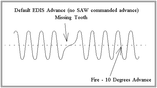
When the EDIS module receives proper a VR signal, it generates a 12-volt square-wave signal with a period linked to the next cylinder to fire. In other words, when this signal (Ford calls it the PIP, for Profile Ignition Pick-up) goes from +12V to ground, one of the ignition coils is firing. This signal follows the ignition coils, not the VR sensor (as indicated on some incorrect documentation floating around).
For an EDIS-8 module, there will be four complete cycles of the PIP waveform for every 360 degrees crankshaft, or thirty-five VR signal cycles (not 36 because of the missing tooth). An EDIS-6 will yield three PIP cycles per every 360-degrees crank, and an EDIS-4 gives two.
For example, with an EDIS-8, we have 9 VR sensor cycles (or 8 if the 'missing tooth is in that sector) for every 90° of engine rotation, and this corresponds to the period between coil firings (on two cylinders, one of which is wasted). So during this period, the coil has started low, gone to 12 volts to charged the coil, then gone low (grounded) to fire the plugs. The duration of the PIP signal is based on the desired coil dwell period, and is calculated internally by the EDIS module.
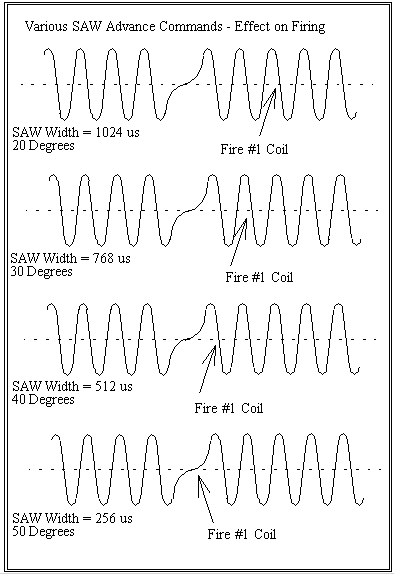
The spark advance is controlled by the Spark Angle Word (SAW) line on the EDIS module. The SAW is a pulse width of a specific duration that tells the EDIS system when to fire the spark plugs. It is calculated as follows:
where:
- SAW is the calculated pulse width (in microseconds);
- ZTDC is the pulse width offset corresponding to the SAW pulse width for a spark advance of 0° TDC;
- ST is spark advance in degrees, and is negative for spark angles after top dead center (ATDC);
- T is the pulse accumulator clock period (in microseconds);
- 2.sup.x is the number of steps between position signals for a desired spark resolution and x is a whole number; and
- CMI is the engine crank marker interval, i.e., the number of degrees of crankshaft rotation between signals from the position sensor.
A top dead center offset value is selected as 1536 microseconds (i.e., ZTDC=1536). A clock period of four microseconds (4µsec) is used in the pulse accumulator, corresponding to a clock frequency of 250 KHz. The crank marker interval is 10° and a desired resolution within the 10° intervals is chosen as 64 discrete steps, i.e., x=6. The formula for determining SAW pulse width is thus:
| Range: 64 - 1792 µsec (57½° BTDC to 10° ATDC) Resolution: 4 µsec (5/32 of a degree) |
For example, for 36° of advance, we want MegaSquirt-II to send a SAW of:
The width of the SAW word in degrees is related to the desired advance by the above equation. At first glance, it looks odd, but it does make sense (depending on the hardware generating the width). With a microcontroller timer peripheral, most timers use a counter 16-bits in length, and they have a mode known output-compare, which is used to make an output toggle when the counter reaches a comparison value. Using a 16-bit timer incrementing at a 1 microsecond rate, and a 16-bit comparison register to toggle the output, one can easily generate the required period. In fact, the numbers are quite easy to use - see the following table for example SAW advance widths and corresponding 16-bit timer compare values:
| Advance Degrees | SAW Pulse Width (µsec) | High-order 8-bits | Low-order 8-bits |
| 10° | 1280 | 0x05 | 0x00 |
| 20° | 1024 | 0x04 | 0x00 |
| 25° | 896 | 0x03 | 0x80 |
| 30° | 768 | 0x03 | 0x00 |
| 40° | 512 | 0x02 | 0x00 |
| 50° | 256 | 0x01 | 0x00 |
| 55° | 128 | 0x00 | 0x80 |
The numbers now make a little more sense. The high-order of the 16-bit timer drives every 10 degrees, and the lower 8-bits drives the advance values in-between. This makes generation of advance widths very easy with a microcontroller. The Ford engineers knew what they were doing!
The PIP signal is used as a reference to synchronize the generation of the SAW pulse by MegaSquirt-II™. The SAW signal is generated by MegaSquirt-II and is an input to the EDIS module. This signal is a +5V positive square wave pulse, and the width of this pulse determines the advance that the EDIS module will use for subsequent ignition events, up to a half second or so. If the SAW signal is lost for much longer than this, the 'limp-home' mode is enabled, and advance is set at 10° BTDC. So the SAW signal does not have to be sent on every PIP cycle - the EDIS module will remember the last SAW commanded advance and "remember" it for subsequent ignition advance values until a new pulse is received or until 'limp-home' mode is enabled.
Note that the SAW pulse must be synchronized with the PIP negative going pulse (i.e, when the PIP drops to zero). It cannot be applied asynchronously to the PIP signal, otherwise incorrect advance commands will be interpreted by the EDIS module. SAW should be initiated a short period after the falling edge of the PIP signal.
Here is the proper relationship between the two signals:
The range of the spark advance word is from 59° (60° would be a pulse width of zero, and the previous SAW would be used) down to 0°. How does one measure this? Using a two-channel scope and monitoring the VR waveform and coil #1 output from the EDIS module, it is easy to see the relationship:
A significant part of the whole EDIS module is the multiple-coil drivers. First thing is that the EDIS module has the actual ignition coil driver built-in - the driver is not part of the Ford wasted-spark coil pack. The coil packs are just standard ignition coils, and could in theory be substituted with other coil-only packs. The EDIS-8 module has four coil drive channels - EDIS 6 has three, and the EDIS-4 has two. The EDIS module handles the dwell time automatically, depending on commanded advance and RPM - another feature which makes the EDIS one of the easiest to use DIY setups.
The EDIS ignition system is rugged. The module mounts under-hood and will survive engine-bay temperatures, water, freezing, etc. And with only two wires going back to the MegaSquirt-II box (PIP and SAW), wiring is extremely easy.
Installing the Ford EDIS System
Note that the PIP signal from the EDIS module to your MegaSquirt® controller is like a Hall sensor signal (positive only square wave). As a result, you use the Hall input circuit, On a V3 board, jumper D1 and D2 (or install jumpers in their place when assembling).
The SAW signal from your MegaSquirt® controller to the EDIS module comes out on pin #17 of the 40 pin socket (labeled IGN), and is connected to the 5th hole of the JP1 socket (pin 8 of the MC9S12C64) on V2.2 boards (JS10 on V3.0 boards). The PIP signal goes to MegaSquirt-II via the DB37 pin 24. This is connected to pin 14 of the 40 pin socket (IRQ), and pin #1 of the MC9S12C64 processor.
To install EDIS with your MegaSquirt® controller, you connect:
V2.2 main board:
If you are using the relay board with a v3 main board:
Here are the EDIS pin-outs for the EDIS4, EDIS-6 and EDIS-8:
Note that the EDIS-4 and EDIS-8 key are similar, but swapped from end to end. Do not attempt to connect them, you will ruin the module, wiring, and/or coil packs. In all case the clip is the most useful guide to the pin numbering. Pin #1 is usually marked on the connector.
Spark Plug Wiring
There are a number of principles to wiring the spark plug leads to the coils, and a number of 'gotchas'.
Note that most timing lights that let you set the timing with a dial and read the alignment of fixed TDC marks with the strobe will not work with EDIS. This is because these timing lights use the time between sparks to compute the engine speed and advance, but the EDIS wasted spark is giving sparks twice as often as the timing light expects for a given rpm. If you have a 'dial back' timing light, set the dial to zero and use a degreed damper or timing tape to view the advance.
In TunerStudioMS, set:
Set the predictor algorithm option to 'last interval'.
DO NOT set the missing tooth settings to 36-1 - set the Trigger Wheel Teeth to zero - the EDIS module takes care of the 36-1 wheel - your MegaSquirt® controller sees it as a regular distributor.
For your dash tachometer, you have a few choices, :
If you are running EDIS on a Ford engine, you may also be interested in controlling the PWM Idle vale: IAC.htm#pwm