| |
| |
In order to make your MegaSquirt® work on a vehicle, you will need the following additional fuel system items to suit your installation:
Note that if you start by installing MegaSquirt® with a throttle body injection unit from a late model vehicle, it will likely come with the injectors, pressure regulator, and throttle position sensor; this will greatly simplify the installation of MegaSquirt® on a vehicle that was previously carbureted. If you choose a TBI unit, you will not need as much wiring, fuel rails, manifold modifications for injector bungs, etc. Once you get the TBI set-up working, you can later switch to port injection and use the TBI as an air door only.
In order to properly install your MegaSquirt® EFI Controller, you need to select and install fuel system components appropriate for your engine. Most important is that you have fuel injectors that are the correct size in terms of flow rating. In fact, most injectors are a similar size physically, though there tends to be more variation in throttle body injection injectors than in port injectors. Typical dimensions for a port injector are:
Here are two TBI injectors. One the left is a Holley 85 lb/hr TBI injectors (apparently similar to some Chrysler TBI injectors), on the right is a GM TBI injector from a 1984 Corvette:
Injectors that have too large a flow rating will make it difficult to tune the engine at idle and cruise. Injectors that have too small a flow rating can starve the engine of fuel at full power, and seriously damage your engine. To determine how big your injector's flow rating should be, multiply estimated horsepower (HP) of your engine by the brake specific fuel consumption (BSFC)* and divide by the number of injectors and the desired duty cycle and you will get a rough estimate of injector size:
InjectorSize = (HorsePower * BSFC) / (#Injectors * DutyCycle)
for example, a 135 horsepower gasoline fueled 4 cylinder engine with 2 throttle body injectors and 0.55 brake specific fuel consumption gives:
(135 HP * 0.55 lb/hr/HP) / (2*.85) = ~ 43.7 lb/hr
Injectors rated between 42 and 45 lb/hr would be okay in this case.
*BSFC is the amount of fuel your engine uses to make 1 horsepower for one hour. It is usually between 0.42 and 0.58 at wide open throttle. Normally aspirated engines with efficient combustion processes are at the lower end of the BSFC scale [~0.45], supercharged engines tend to be towards the higher end [~0.55].
To save a bit of calculation, you can enter your engine's estimated brake horsepower (at the flywheel) and the total number of injectors in the form below and press the "Compute Flowrate" button.
Or you can use the following chart to select injectors based on the total horsepower of your engine and the total number of injectors:
in lbs/hr and (cc/min) | ||||||
|
| |||||
| 1 | 2 | 4 | 5 | 6 | 8 |
100 | 59 (620) | 29 (305) | 15 (158) | 12 (126) | 10 (105) | - |
150 | 88 (924) | 44 (462) | 22 (231) | 18 (189) | 15 (158) | 11 (116) |
200 | - | 59 (620) | 29 (305) | 24 (252) | 20 (210) | 15 (158) |
250 | - | 74 (777) | 37 (389) | 29 (305) | 25 (263) | 18 (189) |
300 | - | 88 (924) | 44 (462) | 35 (368) | 29 (305) | 22 (231) |
350 | - | - | 51 (534) | 41 (431) | 34 (357) | 26 (273) |
400 | - | - | 59 (620) | 47 (494) | 39 (410) | 29 (305) |
450 | - | - | 66 (693) | 53 (557) | 44 (462) | 33 (347) |
500 | - | - | 74 (777) | 59 (620) | 49 (515) | 37 (389) |
550 | - | - | 81 (851) | 65 (683) | 54 (567) | 40 (420) |
600 | - | - | 88 (924) | 71 (746) | 59 (620) | 44 (462) |
|
based on 0.50 BSFC and 85% duty cycle Turbo/supercharged engines should add 10% to listed minimum injector size | ||||||
Injectors are usually rated in either lbs/houror cc/min. The accepted conversion factor between these depends somewhat on fuel density, which changes with formulation (i.e., by season), but the generally used conversion for gasoline is:
1 lb/hr ~ 10.5 cc/min
You can use this converter:
Another way to select injectors is to take them from an engine that makes nearly the same power as your engine will [assuming the same number of injectors].
If your regulator is adjustable (many aftermarket ones are), you can also adjust the fuel pressure to achieve different flow rates. Changing the fuel pressure doesn't affect the flow rate as much as you might assume, since it is based on the square root of the pressure ratio. The formula is:
So for example, if you had 30 lb/hr injectors rated at 43.5 psi, and you went to 50 psi, you would get:
You can use this calculator:
Do not run more than 70 psi fuel pressure, or the injectors may not open/close properly.
However, do not install injectors with a much larger flow capacity than you need. Very large injectors will create idle pulse width issues that will make tuning very difficult. You can estimate your idle pulse width beforehand. For proper tuning, you will need an idle pulse width of at least 1.7 milliseconds. To calculate the idle pulse width, recall that the fueling equation for MegaSquirt® is:
So, find the REQ_FUEL that corresponds to your injector's flow rate and engine size. There is a REQ_FUEL calculator in MegaTune, and also here. If you have the engine running, you can check the MAP at idle (or you can guess - pick about ~25 kPa for a stock cam, ~35 kPa for a performance cam, ~45 kPa for a race cam). Then you only need the idle VE (and injector open time) to predict the idle pulse width, since this is minimum when there are no enrichments (E=0, accel=0). Note that you need to use the 'downloaded' REQ_FUEL, which is adjusted for the number of injectors and their staging.
A good "rule of thumb" for idle VE is 30%. You may actually be 20% or 40% depending on things like compression, overlap, ignition timing, etc., but 30% will be close enough to give you a good idea about idle pulse width. And use 1.0 msec for the injector opening time, unless you have a very good reason to do otherwise.
For example, on one engine:
And the measured idle PW was 1.7 msec. So these injectors are okay on this engine, but just barely. If it had been 1.2 or 1.3 milliseconds, these injectors would have presented very significant tuning problems on this engine.
Injectors frequently have identifying numbers stamped on them. You may be able to identify your injectors by looking on:
http://www.geocities.com/MotorCity/Pit/9975/dataBySubject/Injectors.html
or
http://www.telusplanet.net/%7Echichm/tech/injectors.pdf
Injectors should not be used at more than 80-85% duty cycle. However, injector rates are always specified at 100% duty cycle and some nominal pressure (usually 43.5 psi = 3 atmospheres). The manufacturer leaves it up to you to determine a system pressure and maximum duty cycle in order to compute the resulting flow.
Injectors are driven by an electrical signal from MegaSquirt® that grounds the +12 volt supply through the injectors to open them. Once they are open, they flow at a constant rate until closing. The amount of time required to open and close the injectors is specified in MegaSquirt® as the 'Injector Opening Time' (usually about 1.0 msec). Here is an example of a low impedance injector's pulse voltage, current, and fuel flow:
Injectors are either high impedance or low impedance. High impedance injectors (usually about 12-16 ohms) can take a 12 supply directly, without a form of current control. Low impedance injectors (generally below 3 ohms) require some form of current limiting. With MegaSquirt® EFI Controller, you can use resistors to limit current, or you can use Pulse Width Modulation (PWM), which is a software solution built in to MegaSquirt®.
PWM works by switching the 12 volt ground to the injector on and off very rapidly (in about 0.000059 seconds!). The ratio of the "on" time to the "off" time determines the current through the injectors. However, the easiest way to think of the PWM% is as a percentage of the supply voltage, so 50% PWM on a 14 volt supply becomes effectively 7 volts on average, 28% would be 4 volts, etc.
Remember that pulse width and PWM% are two different things. Pulse width is the total duration of the signal whereas PWM% is the ratio of 'on-time' to 'off-time' within the pulse. So in the above illustration, the pulse width for both is the same, but the PWM% for the first is 50%, while for the second it is 25%.
The PWM% you will be able to use depends on the flyback circuit you have. Version 2.2 hardware generally requires about 55% to 75% PWM. Often the engine will run with lower values, but will not have enough voltage to re-start. Note that using embedded code version 2.986 or higher will disable PWM during cranking, allowing somewhat lower PWM% values. The FlyBack Board allows you to lower the PWM% dramatically, generally to 30% or less. It also helps close the injectors faster.
With better flyback control, you can reduce injector opening times (recall that the injector opening time is really the sum of the opening and closing times), and increase the duration of the 'controllable' part of the pulse width (i.e. after the opening time),
The important thing about the injector open time is that it sets a lower bound for the pulse width (regardless of whether PWM is on, etc.). so if you have injector opening at 1.7ms, you cannot set it to 1.6 or anything lower, even with VE=0. MegaSquirt® assumes no fuel is injected during this time, but some is, though it is hard to calculate how much. The longer it takes to open, the more fuel is likely injected during opening. With lower opening times (by allowing full voltage (i.e. no PWM), you can get the injectors open quicker.
Your engine will need a certain amount of fuel to run correctly at idle when fully warmed up. If this amount is below that injected during the injector opening time, you will always be rich and have no way to lean it out, short of reducing the fuel pressure.
Note that PWM is disabled (in v2.986 code) during cranking so the injectors get full battery voltage. This makes 'severe' starting conditions (lower cranking voltages, etc.) less likely to result in the injectors not opening. This is not possible with resistors, unless you devise a way to bypass them during starting (like the older cars did for the ignition coil).
When using low-impedance injectors, which are also called peak and hold injectors (P&H), you wire them in parallel. The wiring is the same for P&H or saturated [high-impedance].
To exceed the recommended number of injectors (see below) either requires resistors in series with each injector or a modified flyback setup.
The following is a guide as to whether you need to use resistors or the flyback board:
(total) | Hardware |
| |
High (12 - 16 ohm) | up to 12 | V2.2 | no PWM current limit |
Low (> 2.4 ohm) | up to 4 | V2.2 | use PWM current limit |
Low (> 2.4 ohm) | more than 4 | V2.2 |
or flyback board |
Low (< 2.4 and > 1.2 ohm) | more than 3 | V2.2 | or flyback board |
Low (< 1.2 ohm) | up to 2 | V2.2 | use PWM current limit |
Low (< 1.2 ohm) | more than 2 | V2.2 | or flyback board |
One sure way to know if you can't use the standard V2.2 flyback circuit is to have a flyback failure. The circuit will most often fail after some time spend at high speeds and loads, rather than immediately when you start the engine for the first time. Generally, when the flyback circuit fails, the MegaSquirt® works okay on the stim, but not on the car.
Signs of an impending flyback failure are:
When the flyback fails, sometimes Q1 (the TIP32 on the bottom of the PCB) looks pretty rough, all burnt, etc. However sometimes it looks fine.
If Q1 (on the bottom of the board) does look burnt however, this is a sure sign of a flyback failure. To repair after a flyback board, you need to adopt the flyback board, or use injector resistors.
To use the flyback board, you will discard many of the original V2.2 flyback components, so don't replace anything until you install the flyback board. However, if you are going to repair the V2.2 flyback circuit and use injector resistors, you need to replace a number of components:
The resistors and diodes of the V2.2 flyback circuit seem to survive the flyback failure generally, though you could order and replace them to be sure (they are reasonably cheap).
They are:
In order to prevent future flyback failures, you can adapt either the flyback board or injector resistors. The flyback board:
However, resistors are:
For example, the injector resistors 825F7R5-ND are $4.66 each. The flyback board ($12) and components ($6.86) total $18.86, so the 'cross-over' point is 4 injectors, using new components (depending on shipping, etc.). Of course, if you source your resistor pack from a scrap yard, or if your vehicle already has them, this is cheaper!
People running a number of very low impedance injectors on V2.2 main boards have reported problems with the flyback circuit failing. Typically, this will happen with 4 or more low-impedance injectors, such as the Holley 85 lb/hr TBI injectors. This can be avoided by using resistors in series with the injectors, and disabling the pulse width modulation (PWM). However, a more elegant solution that continues to use PWM is the Flyback Board.
The Flyback board is an additional 'daughtercard' for MegaSquirt® V2.2 main boards that does a number of things:
The V3 main board has the flyback circuit built in.
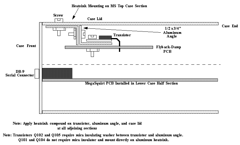
The Flyback Board installs in the up half of the MegaSquirt® case. It slides into the lowest slot, and is attached to a substantial heat sink (that you make yourself from ½"x¾" aluminum angle). Six 20 to 22 gauge wires (two injector banks, two CPU [X0, X1], +12 volts, and ground) connect the Flyback Board to MegaSquirt. The Flyback board must be used in conjunction with embedded code version 2.986 or higher. This code has the proper switching code to turn the Flyback circuits on after PWM ends.
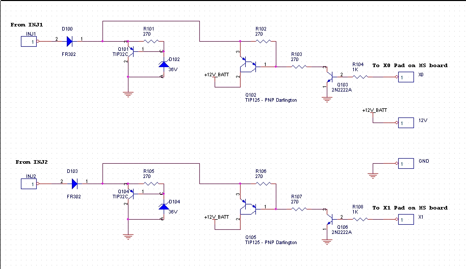
This is the schematic for the FlyBack board:
To assemble the flyback board, follow these instructions:
1) Disable the existing flyback circuit. You can do this by cutting the leads to D22 and D23. You can remove the remaining flyback components if you wish. They are: R32 (270 ohms, ½ watt resistor), Q1 (TIP42 transistor), and D21 (36 volt Zener diode). Removing components is easiest if you cut the leads, then remove each lead separately. This puts less heat into the board and other components.
2) If you are upgrading your flyback components because of a flyback failure, replace the 34151 FET driver IC, and the two FETs (IFRIZ34) as well.
3) Install and solder R101, R102, R103, R105, R106, and R107. All of these are 270 ohm, ½ watt resistors {270H-ND}. 4) Install and solder R104 and R108 {1.0 Kohm, ¼ watt}.
5) Install and solder D100 and D103 {fast recovery diodes, FR302DICT-ND}. Be sure to orient them with the banded end as shown on the silk screen.
6) Install and solder Q103 and Q106 {transistors, PN2222AD26ZCT-ND}. Note that the flat side faces to the left when the silk screen printing is oriented so that you can read it. You have to bend the middle leg slightly towards the flat side to fit it in the holes. 7) Install and solder D102 and D104 {36 volt Zener diodes, 1N4753ADICT-ND}. Be sure to orient them with the banded end as shown on the silk screen.
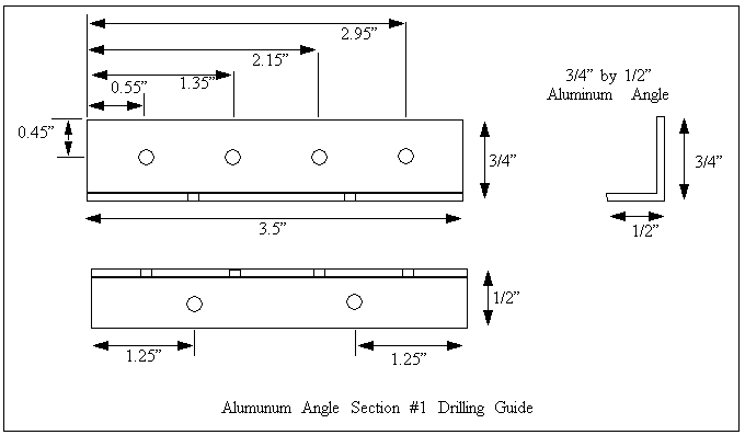
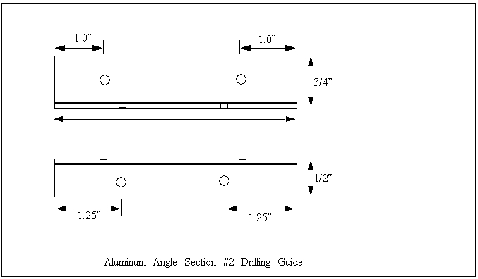
8) Before installing the four T0-220 transistors, you need to fabricate the heat-sink. You need two 3½" (89mm) long pieces of aluminum angle that are ½" by ¾" (13mm x 19mm), about .040" to .080" thick (1.0mm to 2.0mm). Drill (1/8" - 3mm) these as indicated below:
Make sure your heat sink is no longer than 3½" (89mm), so that it can sit flat against the case. The edge of the heat sink is flush with the end of the case. Drill corresponding holes in the case. Be sure to drill the correct end of the case (the DB9/LED end). Verify that the heat sink will sit flat when bolted to the case. The heat sink is design to attach to the FlyBack board by the four transistor mounting holes. The heat sink should just be tall enough to allow the FlyBack board to slide underneath it when it is installed in the lowest slot of the upper case. Make sure to get the heat sink dimensions correct - otherwise you could stress the FlyBack board and/or impair the heat conduction abilities of the FlyBack board. Either could lead to failure.
9) Assemble the heat sink (but do not fasten it to the case) as shown below using ½" (13mm) #4-40 machine screws and nuts: 10) Bends the leads of the TIP125 Darlington transistors Q102 and Q105 so that the mounting holes and leads line up with both the PCB and heat-sink. Make sure the leads of the transistor will not touch the heat sink! The heat sink is sandwiched between the transistor body and the PCB.
Apply heat sink compound between the two angles, and also between the transistors, mica, and heat sink. Bolt the transistors in place using #4-40 machine screws and nuts using a mica insulator kit between each transistor and heat sink. Be sure to place the bolts for the transistors/heat sink through the bottom, and the nuts on the top, as clearance is limited.
You might have to trim the mica with a sharp pair of scissors to make it fit properly. Solder the transistor leads in place.
Use a multi-meter on its highest resistance setting to check that you have "infinite" resistance between the metal mounting tab of the transistor body and the heat sink. If this is not the case, your insulator is not insulating. Find out why. You may have to de-burr the transistor mounting holes in the heat sink (you can counter sink them with a quick touch of a ¼" drill). You can also sand the surface of the heat sink lightly where the transistors bolt on. Be sure to thoroughly clean the heat sink afterwards.
Do not proceed until you have electrically isolated the TIP125 transistor mounting tab from the heat sink. 11) Bends the leads of the TIP32C {TIP32CFS-ND} transistors Q101 and Q104 so that the mounting holes and leads line up with both the PCB and heat-sink. Make sure the leads of the transistor will not touch the heat sink!
Apply heat sink compound between the two angles, and also between the transistors and heat sink. Bolt the transistors in place using #4-40 machine screws and nuts. These transistors do not need a mica insulator. Be sure to place the bolts for the transistors/heat sink through the bottom, and the nuts on the top, as clearance is limited. Solder the leads in place.
12) Run a 20 to 22 gauge jumper wire from X0 on the MegaSquirt® PCB (near the CPU) to X0 on the Flyback PCB. 13) Run a 20 to 22 gauge jumper wire from X1 on the MegaSquirt® PCB (near the CPU) to X1 on the Flyback PCB. 14) Run a 20 to 22 gauge jumper 12 volt power wire from the unmarked through hole just to the right of X13 (and slightly below) on the MegaSquirt® PCB to the hole marked 12V on the right side of the FlyBack PCB.
15) Run a 20 to 22 gauge jumper ground wire from the unmarked through any of the holes for the 'non-banded' end of the unused diodes (at D1, D2, D3, or D4) on the MegaSquirt® PCB to the hole marked GND on the right side of the FlyBack PCB. For example, if you use D4, install the ground wire from the end of D4 closest the CPU to the hole marked GND on the FlyBack PCB. 16 a.) Connect a 20 to 22 gauge wire from the hole at the non-banded end of D22 (the one you removed) on the MegaSquirt® PCB to the hole on the Flyback PCB marked INJ1.
16 b.) Connect a 20 to 22 gauge wire from the hole at the non-banded end of D23 (the one you removed) on the MegaSquirt® PCB to the hole on the Flyback PCB marked INJ2. 17) Install the heat sink and FlyBack board into the case. The board slides in the first slot in the case. Apply heat sink compound between the case and heat sink. Use #4-40 screws to fasten the heat sink. You may need to bend any of C12, C15, C17, C18, C19, C22, C23, and/or C24 over a bit to get enough clearance, depending on how much lead length you left when they were originally soldered in.
18) Make sure to load version 2.98 embedded code or higher into your MegaSquirt. 19) Reset your PWM parameters. Try 30% and 1.0ms to start, then "tune" them as described in the manual. 20) Reassemble your case, and you are ready to go! Be careful not to 'pinch' any of the connecting wires between the two halves of the case when you reassemble.
Note, if you assemble your flyback board, but find that it won't allow your engine to run with less than ~75% PWM, the flyback board is NOT working. You need to find out why. You can:
However, instead of the flyback board, you may choose to use resistors in series with your injectors. Several people reported that resistors do NOT result in significantly longer opening times, or any other troublesome effects, so this is a good solution for many installs. To eliminate PWM altogether, use a 5 to 8 ohm resistor (with a 20 to 25 watt rating) in series with each injector.
If you want to avoid using PWM with your low-impedance injectors, you can use ballast resistors in series with the injectors. You should use one resistor (20-25 Watts) in series with each injector, otherwise the injectors may not all draw the same current, and the failure modes become complicated and difficult to diagnose. As well, you would need a very large resistor to handle more injectors. For example, if you allowed 2 Amps through four 1.2 Ohm injectors wired in parallel (0.3 Ohms total) to one 7 Ohm resistor, the power dissipated would be:
If you use resistors that limit injector current to less than 2 amps, you can disable the PWM mode (by setting PWM% to 100%, and time threshold to 25.4msec) and treat the system as high-impedance. To limit the current to under 2 amps, you need: resistor ohms =
(alternator voltage / 2.0 amps) - injector resistance For example: resistor ohms =
(14.0 volts / 2.0 amps) - 1.2 ohms
=> resistor ohms = 7.0 - 1.2 =
5.8 ohms You can also use the calculator below. Enter your injector resistance in ohms, your hold current in amps, as well as your injector impedance in ohms, in the form below and press the "Compute resistor" button.
The 25-watt resistors aluminum case Ohmite resistors (with 1% tolerance) from www.digi-key work well. Below is a picture of
a 7.5 ohm resistor, Digi-Key part number 825F7R5-ND.
Ohmite has several suitable
resistors, with part numbers that start 825F (25 Watt, aluminum case with
mounting ears) and end in XRY, where X and Y indicate X.Y ohms. Depending on
injector, pick 2-8 ohms or so.
You may prefer to use an OEM injector resistor box instead of making you own set-up. To find out more, see the article "Fuel Injector and Resistor Box Basics - Wrenchin" from Honda Tuning Magazine.
You may be able to use less resistance to protect the flyback components - just a few ohms combined with PWM may do the trick. Be sure to use one resistor in series with each injector, and then you can parallel these into the two banks. Do not share two or more injectors per resistor, use a resistor per injector.
There a lower bound to the pulse width, below
which a low impedance injector cannot be expected to reliably function. There
are two problems with running the very lower pulse widths that result from
large injectors. There is a limit on the physical ability of the injector to
opening and close as quickly as possible, and there is also a limit to the
ability of the MegaSquirt® controller to adjust the pulse width to an optimum
value at very low pulse widths.
The absolute physical limit depends on your
particular injectors and the hardware that controls them. Some are able to go as
low as 1.1 to 1.5 milliseconds [ms]. Note that there are three components to
the injection duration - the opening time, the commanded pulse, and the closing
time. Ideally you would want the opening and closing times to be a short as
possible to have the controller determining as much of the amount of the time
injected as possible. The opening time is difficult to adjust given a certain
operating voltage. The closing time, however is controlled to a degree by the
flyback circuit in the MegaSquirt.
With very large injectors [for a given application],
the idle pulse widths may be around 1.0 millisecond. This is a problem because
in the standard code for MegaSquirt-I, the resolution of the steps is 0.1 ms. So
a 1.1 millisecond “squirt” will only be able to be adjusted in ~9% increments
(i.e. 1.0, 1.1, 1.2 etc.), which may be too coarse to get a good idle. The
high-resolution MegaSquirt-I code can help in this situation, but you lose the
PWM current limiting mode so you have to run resistor packs with peak and hold
low-impedance injectors.
An ideal idle duration is around 2.3 ms, and this
is approximately where properly sized injectors should operate. This gives good
resolution [~4%], and you should be able to get a real good idle.
You will need to acquire connectors for wiring
the MegaSquirt® to your injectors, etc. Niehoff has individual injector
connectors under part number 28419 (connector) and 28418 (sealing
boot). On the web, Waytek has lots of different connectors that you can use in
building your MegaSquirt. Their prices are about as cheap as you can find. The
injector connectors are AMP part number 827551-3, but sometimes you have
to buy a large quantity. Also try DelCity. They are not quite as cheap, but
they may have stuff you cannot get from Waytek. You can get information on injector bungs for port injectors by checking out www.sdsefi.com for injector/manifold installation information, along with lots of other great information. The bungs are 0.530"-0.535" inside diameter [about 17/32" or 13.5 mm]. The fuel supply lines for the top of the injectors are the same size. VERY IMPORTANT! If you do not own at least two
fire extinguishers, go buy some right now! Experimentation with EFI can be very
dangerous because you are playing with high pressure gasoline. Install at least
one fire extinguisher in your work area (away from where the fire is mostly
likely to occur) and carry another one in your car. Do not ignore this advice.
We do not want to be visiting you in the hospital or worse!
MSD and others have an “Epoxy-In Pocket” fuel injector bung as PN 2120 (set of 8). Holley also offers them as PN 534-83 for a four pack (~$50), 534-84 for a pack of six (~$72), or 534-85 for a pack of eight (~$94). These bungs can be held in place with epoxy or welded and is used for fixed fuel rail systems only. These bungs are CNC-machined from aluminum for precise dimensions and have a ¾” OD. Internally, the pockets are contoured to accept the bottom sealing O-ring of a
standard injector. MSD also has “Thread-In Pockets”. The aluminum pockets will screw into a ¾”–16 hole and are supplied with a #8 O-ring to seal the pocket to the
manifold. PN 2125 gets a set of 8.
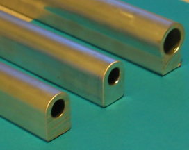
Fuel Rails Most injector systems will use one or more fuel rails. These serve two functions: they supply fuel to a multiple number of injectors (4 on a 4 cylinder, for example), and they physically locate the tops of the injectors. Most OEM rails can be made to work with standard engine configurations, but if you are doing a custom conversion you may have to fabricate fuel rails. Many place supply blank aluminum fuel rail extrusions in whatever length you need. One example is Ross Machine. They have two styles of fuel rail extrusion. They can also create custom fuel rails for you, with the injector holes placed to suit you.
The aluminum extrusion comes in two sizes: For fabricating fuel rails, MSD has “Fuel Delivery Top Mounts”, PN 2115, set of 8. These fuel delivery mounts are CNC machined from #304 stainless steel for great
durability and precise dimensions. They slide over ½” steel tubing (MSD PN
2205) then are brazed or TIG welded in place to form a fuel rail. Fuel is
routed through a 5/16” hole aligned to the mount and the injector. The PN 2105
Fuel Rail Clip is required for assembly. Their “Stainless
Steel Fuel Tubing”, PN 2205, comes in 2 four feet lengths of 304 stainless
steel tubing, and is perfect for making custom fixed rails. The seamless tubing
has a ½” OD and .035” wall. Your throttle body choice depends on whether you are going to use throttle body injection or port injection. Your throttle body needs to do 2 things:
Some people use the complete individual runner (IR) throttle body and injector set-ups off late model motorcycles - they often have enough flow for automotive engines, and are frequently available cheaply on eBay. However, if you are planning on a throttle body injection set-up, you need a dedicated TBI unit (in order to supply the fuel to the injectors, etc.), which can be hard to find for larger engines - Holley has made a 4bbl TBI for years (in 650, 700 and 900 cfm sizes), and as the computer fails regularly on these, they are sometimes available separately on eBay. TBIs have the advantage of having the fuel pressure regulator built in.
Note that for either port or throttle body injection you can use multiple throttle bodies to support your power levels, if your manifold configuration can be adapted for them. When selecting a throttle body, there are a number of considerations. You need it to flow enough to support your engine's horsepower (or more correctly, to not restrict your engines power). Generally, you want to take the throttle body from an engine that made similar horsepower to your engine. However, if you are uncertain of your throttle body's application, you can measure the throttle bore size. However, you can't really compare the throttle of an EFI throttle body to the throttles of a carb. This is because the throttle(s) of a EFI TB is the main restriction, but on a carb, it is the venturis that are the main restriction. So you really have to compare the EFI throttle size to the carb's venturi size. However there are also a number of other considerations, such as that you can go larger with a EFI TB than a carb without suffering so many adverse effects because a vacuum signal isn't needed for the EFI to operate. Fuel delivery is always good with EFI (well, mostly).
However, there are some drawbacks to a too large throttle body:
For reference, the GM tuned Port Injection engines used throttle bodies with two 48mm throttles. These support about 230 horsepower, however these throttles were not the limiting factor in the power produced by these engines.
To calculate how much horsepower you can make from a given throttle body size, you can use the estimator below:
In order to use MegaSquirt® EFI Controller, you will have to
implement a high-pressure fuel supply system. You MUST understand how to do
this properly, and this manual DOES NOT include everything you need to know. If
you are unsure about your installation, have a qualified mechanic look it over
before attempting to start your vehicle. Fuel Pumps
You will need a high pressure pump with enough
volume at your operating pressure to feed you engine under maximum load.
Typical pressures needed in the neighborhood of ~45 psi for port fuel injection,
~10-20 psi for TBI injection. A port injection pump will work with TBI, but not
vice-versa.
OEMs usually place pump inside the fuel tank. In
an EFI retrofit it is generally easier to use an external fuel pump. Ford used
external fuel pumps on 1989 era 150 trucks which may be a candidate for use.
These are high pressure [port EFI] pumps that will work in most applications.
Econoline vans have these as well. The external pumps used in Ford F150 fuel
injected trucks from the 89-93 model years are Delco EP286. At 12 volts,
the operating pressure is 70-95 PSI with 36-40 gals per hour. The biggest Delco
pump is the EP424, which is 75-90 PSI at 40 gals per hour. EP 268 is a
GM# 25117086, EP 424 is a GM# 25176156."
Here is a picture of the Econoline pump: The Carter pump #P70199 (the outlet is
7/16 standard pipe thread and the inlet is 15/32 clamped hose type fitting or 3/4
standard thread. The specs are 95-PSI max, 68-93 G/Hr wide open). This is the
highest flowing Carter external fuel pump in the book. It will produce up to 95
psi, and crosses over to EP7107 at Kragen for about $80 (unfortunately
one end does not come off like the Carter). You might want the Ford style pump EP7109($80). You will need this if you want to be able to modify ends to be
3/8".
Others have had luck using the external pump from
various fuel injected VolksWagen models (87 VW Fox, for example). Part number
is: Bosch 0 580 254 957 reportedly rated at 90 GPH@ 70PSI, you might
find them for about $130 new from www.germanautoparts.com. This pump consists
of a fuel pump, filter, and an "accumulator". You can leave the
accumulator in place since it does not affect the running volume or pressure,
and on used pumps they are often rusted so you might not want to mess with it. Auto Performance Engineering has many high volume Walbro pumps (and their specifications) on their site.
Fuel Line Steel tubing is recommended, but you MUST have short sections of rubber line in the feed and return lines between the engine and frame to allow for engine movement. The return line should have minimal restriction. For reference, GM systems typically have 3/8" feed lines and 5/16" return lines. You may be able to use your original fuel line as a return line, plumbing a new 3/8" (10mm) line for fuel supply. You can run the return line into the tank, or reroute it to a fitting or nipple you install in the fuel tank filler neck/tube assembly (in which case you may be able to use the original pick-up for your supply line). If you run a new pick-up into the tank, it will need a filter. GM sells a sock-type filter that
is a good fit for 3/8" lines. It is part number 5651702 and costs
about $15.
You may have to fabricate fuel lines for your system. Tubing is available in steel, stainless steel, and aluminum for this purpose. The size is generally given as the outside diameter of the tubing. Unless you have a very unusual combination (or very high horsepower, well over 500+), you should be able to use 3/8" tubing for both the supply and return lines. Buy a good tubing bender (there are numerous styles in various price ranges) so that you don't kink or collapse the tubing while bending it. (You can also bend it over a V-belt pulley, in some cases.) The AN (Army-Navy) 'dash' system of hose and fitting sizing was established many years ago by the American military as a common measurement for hoses and fittings. It designates the outside diameter of the metal tube that is compatible with each size of fitting. The AN dash measure is the standard for performance hose applications. These dash sizes are expressed in 16th of an inch. For example, an -06 fitting is 6/16 of an inch or 3/8", just right for our fuel lines!
Most fittings and adapters in the automotive aftermarket are based on a 37° sealing angle (SAE J514 37° - formerly known as JIC). These are also often referred to simply as AN fittings. Male and female 37° fittings will mate together for a leak-proof connection.
Be aware that there are other similar fittings and adapters that use a 45° sealing surface (SAE J512), such as those commonly available at your local hardware store for flared copper pipe. These 45° fittings and adapters can also be found in some OEM automotive applications. However, although they may look very similar to a 37° fitting, they are not interchangeable. In some sizes, they may thread together (-02, -03, -04, -05, -08, -10), but will not seal properly, due to the difference in sealing surface angles. Be sure you know the sealing angle of the fittings you are connecting!
Abrasion (the rubbing of the hose against some other component) is the number one cause of hose failure. A leaking fuel hose can start a very dangerous fire in your car, so make sure hose assemblies are routed properly to reduce the chance of any abrasion damage. Use a support every 12 to 18 inches (30 to 45 cm) to secure the hose. For chafe protection, be sure to install a grommet at any point a hose passes through a panel or bulkhead. Besides steel or aluminum tubing fuel line, you can also use one of the steel or nylon braided hoses from various suppliers. Generally these use the same AN 'dash' sizing system, and can use appropriate fittings to connect to 37° flare, NPT thread, or other systems.
Note that if you are using a factory fuel rail, you may be able to find an aftermarket adapter to mate your OEM fuel fitting to an AN hose. For example, Accel offers TPI fuel rail fittings (pn 74730, ~$32) for -06 hose that will fit most General Motors TPI fuel injections systems. If you need a simple way to get to a barbed fitting to connect up rubber EFI hose to the General Motors 2 bbl TBI, your local auto parts house probably stocks GM fuel line repair kits in the HELP section. These consist of 9" of steel fuel line in 3/8" and 5/16" outside diameter with an O-ring and Saginaw fittings 14/16 mm, respectively, on one end and a barbed end crimped on the other. The steel lines are about $4.00 each. These pieces thread into the steel adapters on the GM Rochester TBIs. For a complete listing of various fittings with part numbers, etc. try: IMPORTANT: Keep the fuel lines out of passenger compartment and routed safely away from moving or hot parts to avoid damage/excessive heat. For flexible rubber hose use the SAE 30R9 EFI hose which is rated at 250 psi. EFI hose clamps are also recommended rather than gear clamps. Check with someone who knows if you are not sure about your installation. Nobody needs a 50 psi gasoline fed fire to ruin their day!
Note that if you feel your fuel supply is not smooth enough, you can add an accumulator. OEMs often have nice small diaphragm types, or you can plumb in a vertical section of rubber hose tee'd off the supply line (and plugged at the top end). This traps air and uses it to cushion the fuel pressure.
Here is a GM style accumulator (it is about 2" (50mm) long and uses 3/8" tubing):
Or you can make your own:
Fuel filter Use a fuel injection fuel filter rated for the pressure at which your system operates. DO NOT use a universal carburetor filter - the higher pressure of fuel injection systems may cause it to burst! Position the filter downstream of the pump so that a clogged fuel filter will not over heat the fuel-cooled pump.
Fuel Pressure Regulator The vacuum referenced fuel pressure regulator is essential. It provides constant pressure differential between fuel at injector nozzle and manifold air pressure [port EFI] or atmospheric pressure [TBI]. This makes the injected fuel quantity solely a function of the injector open time. If you were to 'cap off' the manifold vacuum port on the fuel pressure regulator, you are reducing the dynamic range of the injectors. This means you will need lower pulse widths at at (giving less control over idle mixtures) and lower flow under boost (restricting the maximum horsepower). So, in general, for port injectors, have the fuel pressure regulator connected to the manifold vacuum is a good thing. There is very little reason not to do it (though some have argued against it for individual runner port EFI set-ups).
If you have an adjustable fuel pressure regulator (FPR), set the pressure with the fuel pump running, but the engine not running - that's your base fuel pressure (it is referenced to atmospheric pressure). The regulator is typically at the far end of the fuel rail (after the injectors), but performs its job anywhere, so long as it is after the fuel pump. However, if you have the regulator before the rails, then the full volume of fuel isn't circulating through the rails. Only the amount of fuel actually injected moves, and the fuel can get quite hot, which may require special injectors, etc. Apparently OEM use special injectors, etc., with returnless systems, which is essentially what one has if they put the regulator before the injectors. This can also create problems trapping air on assembly that can cause issues at first start-up.
If you are using an aftermarket fuel pressure regulator, it is a good idea to also install a pressure gauge, since most of these are adjustable. For TBI, use a 0-30 psi gauge. For port injection use a 0-60 psi or 0-100 psi gauge. Most of these gauges will mount directly on a fuel fitting using a 1/8" NPT thread. These are available from most aftermarket speed parts suppliers, such as Summit Racing or Jegs.
Surge Tank
You only need a surge tank if you are using a low
pressure pump to supply an external high-pressure pump. Some pumps come with an
accumulator after the pump, and these can be left in place.
If you are doing repairs, you might also get a socket for the FET driver AE7208-ND (~35¢), it ensures the FET driver sees no heat during assembly, and makes it easier to replace in the future.
![]()
If it passes all those tests, you have to start looking at
individual components. Often, the flyback board is installed because
of a failure, in which case the FETs and FET driver should probably
be replaced as well.
For port injection, you can convert an existing carb, to do both jobs - the carb already controls the air flow, you have to adapt a TPS sensor to it. You may choose to machine out the venturis, remove the float bowls and fuel circuits if you wish, but that isn't necessary (but may be desirable for a number of reasons, including increased power!).
Dash Size Inch Size Nominal Thread Size 04 1/4 7/16-20 05 5/16 1/2-20 06 3/8 9/16-18 08 1/2 3/4-16 10 5/8 7/8-14 Dash Size Inch Size Nominal Thread Size 04 1/4 7/16-20 05 5/16 1/2-20 06 3/8 5/8-18 08 1/2 3/4-16 10 5/8 7/8-14 
Wiring the Fuel Pump
To activate the fuel pump, MegaSquirt® provides a ground for the fuel pump relay circuit on pin 37. The relay is wired for 12 volts switched from the ignition switch, and the relay is grounded through MegaSquirt® [pin 37 on the DB-37 connector].
MegaSquirt will disable the fuel pump when RPM = 0 and enable while non-zero (cranking/running), except for Version 2.00 (and up) embedded software which will perform a short priming pulse, then shut down the pump if the engine is not running after 2 seconds.
You might want to consider a safety switch in the fuel pump circuit when installing an electric fuel pump. Holley has one (12-810, ~$20) that will ensure the fuel pump will not run unless the engine has oil pressure. It stops the pump from running if the motor stalls with the ignition on. Wiring the switch through the starter solenoid circuit energizes the pump on engine start-up. Once the engine has started, the switch continues to provide power to the pump as long as there is oil pressure to keep the switch turned on.
Note: An inertial safety shut off switch should be installed and used to kill power to the pump upon significant impact to vehicle.
These switches are available in junk yards from EFI Fords. The switch is on the drivers side in the trunk, near the trunk hinge, mounted so that it is between the interior bracing and the rear quarter panel (protected from being knocked around if you stuff your trunk full of stuff). It is mounted with the reset switch straight up. Note switch mounting orientation probably matters.
It is Ford Part # F2AB-9341-AA. The wire going into it is about 14 gauge, so it should be capable of handling the full current of the fuel pump.
The markings on the switch show that it has NO/NC (normally open/normally closed) positions so that it should be able to accommodate any possible fuel pump configuration.