

The V3 main board variable reluctor (VR) sensor input circuit has two pots for adjusting the trigger voltage and the hysteresis.
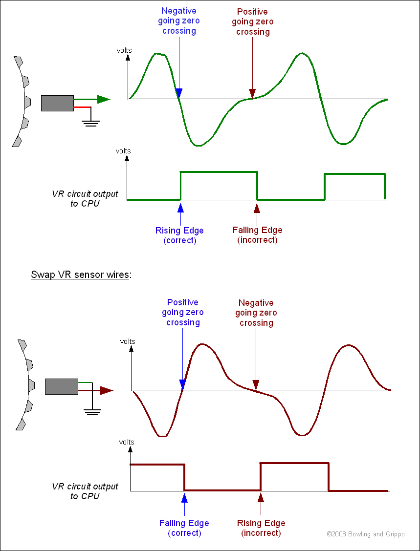
For example, if the VR sensor transitions from negative to positive at the trigger point, going through zero volts (called the "zero crossing") the slope should be steep there. The VR circuit inverts it so the negative-to-positive VR transition becomes a positive-to-ground digital output (VROUT) to the processor IRQ line, and this is what triggers an IRQ (a tach signal).
To adjust the screws for the pots for VR sensor operation, the pot on the transistor base (R56) should be adjusted as near zero as possible (fully counter clockwise), as this is where the VR signal is most stable (all other settings depend on the slope of the signal's rate of change, and hence on the speed of the VR sensor and it's maximum voltage). The pot on the op-amp feedback (R52) needs to be turned to maximize resistance (i.e. give 100K feedback hysteresis). This should be with both screws turned fully counter-clockwise. The pots don't actually stop when fully counter clockwise, instead they have a clutch that lets them spin at the end of their travel. You might be able to hear and feel a slight click when this happens.
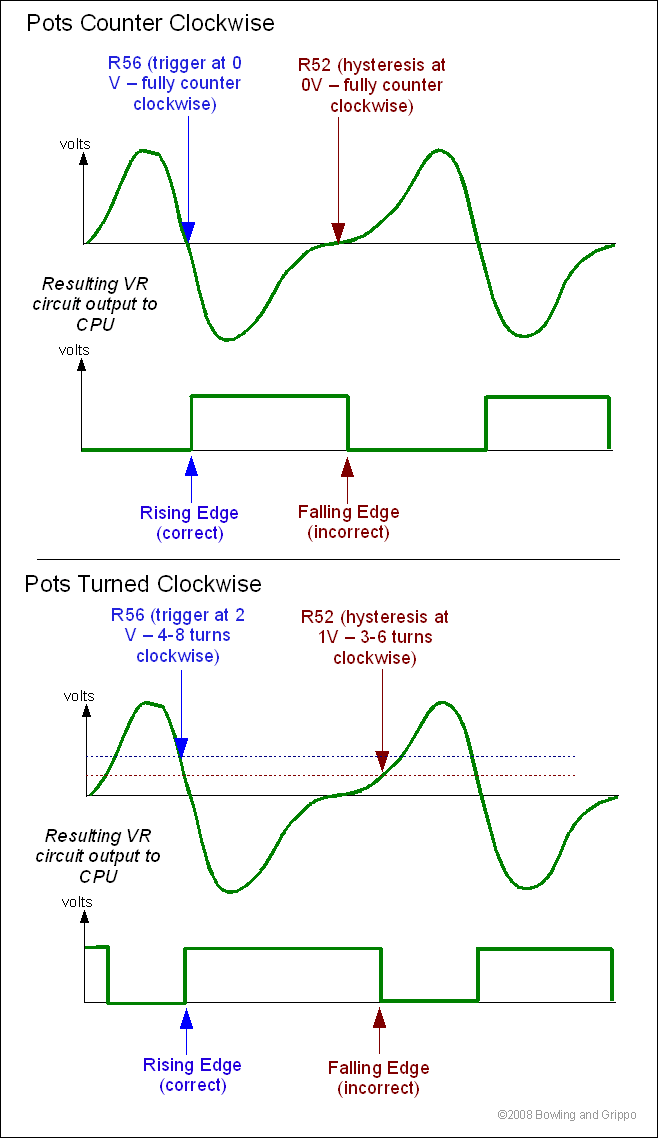
Try this on the car and if there is noise on the tach VR signal then adjust the hysteresis pot (R52) clockwise until the noise vanishes. If you turn it too far there may be too much hysteresis and cranking signal may be difficult to trigger on.
The VR input circuit should be capable of triggering in the millivolt region, if it requires one or more volts to trigger reliably then you should suspect a component or inadequate soldering.
You can improve the common-mode rejection of the circuit (common mode rejection is the ability of the circuit to 'ignore' the effects of noise that occurs on both signal wires at the same time). Here is the first thing to try: take the VR return wire, the one you have been connecting to ground, and put in a series resistance, like 47K or so, and connect the other end of the resistor directly to the wiper of the zero-crossing potentiometer (R56), marked "2 2" in the schematic below, which also goes to the base of Q23 (the "2 2" indicates pin 2 on the pot and pin 2 on Q23). Next move the zero-crossing point potentiometer setting off of zero volts to a point of, say 1 volt or even higher (measure the voltage at the wiper). Since the return point of the VR is also at this junction, the VR sensor will also be biased up the same amount, so the circuit will still sense zero crossing properly. In fact, it does not matter where the zero-crossing pot is set in this case, since the return VR sensor lead will also be biased by the same amount. But what this does is allow rejection of common noise introduced in the VR wires by the op-amp.
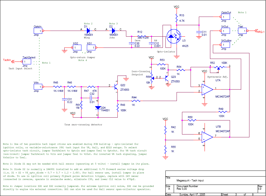
On the other side, the hysteresis pot (R52), even cranked all the way counterclockwise, will introduce a little hysteresis. Removal of the pot will remove all hysteresis and both sides will trigger directly at the "zero crossing". This is the effect of the asymmetric hysteresis, it only affects the positive-to-negative VR direction, not the negative-to-positive direction. The intent is to trigger on the negative-to-positive transition direction, and the VR sensor needs to be wired appropriately.
The VR circuit should also be able to take Hall inputs, EDIS (there is an inverted output available) and ignition coil primary, by setting the threshold and hysteresis trimmer pots to points yet to be determined. The existing MS V2.2 tach circuit with the optoisolator is also there for those who want to stick with this. You can experiment find trimmer adjustment values which will work for the square wave signals from EDIS, Hall, ignition primary, etc.
Note that you must get the VR sensor wired appropriately for your settings:
See pickups for more information.
For a perfect square wave, the pots can be left fully counter-clockwise:
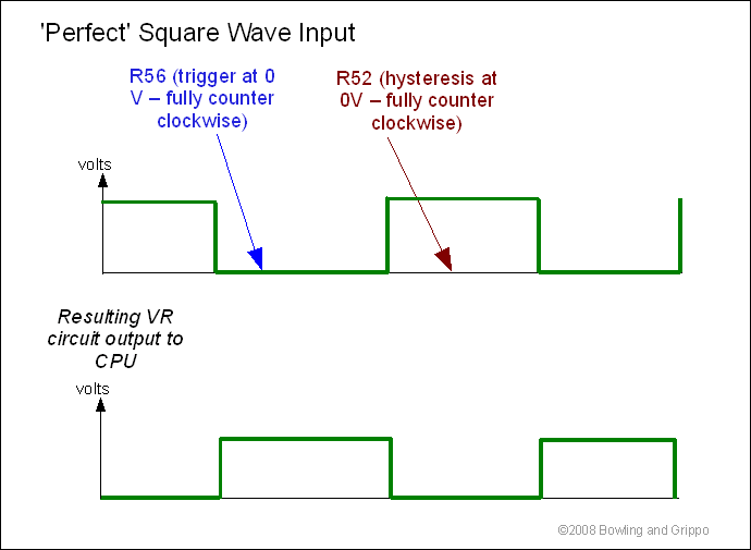
On the stim, and possibly some other squarer wave signals, the stimulator tach output may not go thru zero volts so it may not trigger the VR circuit. The signal may also be noisy. So for operation using the stim, or using the VR circuit for a Hall sensor, the R56 pot will likely have to be adjusted a few turns (or more) clockwise. This is raises the trigger voltage above ground, allowing square wave signals to trigger the circuit. Turn the zero-crossing pot (R56) clockwise until the threshold is raised enough to cause a trigger.
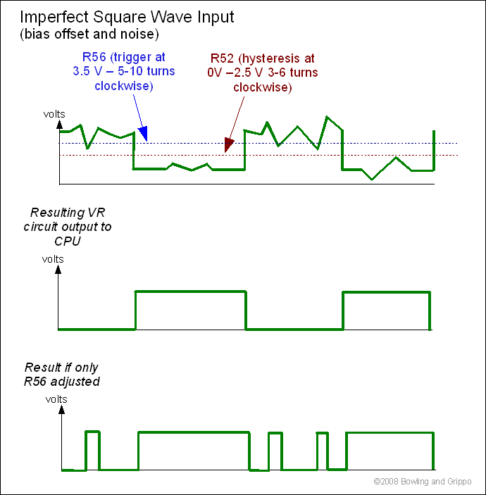
You may have to adjust the hysteresis pot (R52) as well to reduce the effects of noise in the signal.
Note that without trigger pot (R56) pot adjustments, you would not get a signal at all (since the signal never drops to zero, the VR output would stay low). If you adjusted only the trigger pot (R56) the signal would be very noisy, since the output would change every time the signal passed through the trigger voltage. So you would adjust the hysteresis pot to clean up the signal.
If you are using another trigger source feeding the VR input circuit (say the EDIS PIP or some Hall sensors) the polarity may need to be changed, this is when they use the other op-amp output (VROUTINV) instead this polarity follows the VR sensor so a negative-to-positive VR sensor yields a ground-to-positive digital output.