Fuel calculations for the MegaSquirt-II algorithm are performed in the HCS12 processor (such as fuel, ignition, and anything else requiring math calculations). A separate 2916 chip is used to drive the IAC stepper motor.
MegaSquirt-II uses the HC9S12C64 processor from Motorola's HCS12 family of automotive grade processors.
The MC9S12C64MFA LQFP 48 pin version is used for MegaSquirt-II. It has a 0.5mm pitch lead spacing, and a 7mm x 7mm package. This is a true automotive processor with automotive temperature range (-40°C to +125°C). Its original use was for ABS braking systems - millions of these are being used in today's cars. Because it is used for braking control, not only is it tested and rated for automotive applications, it has an extended testing for latchup due to OEM safety requirements (see the specs in the electrical section of the data sheet). It is a true 16-bit processor with a true 16-bit data bus.
The HC9S12C64 processor is optimized for the C language, and MegaSquirt-II's embedded code is written in C. Motorola reports up to 50% increases in code efficiency over other 16 bit architectures. A key benefit of higher code efficiency is the requirement for less memory either integrated onto the processor that can result in reduced component count and costs. The code efficiency is made possible by use of many 8 bit operation codes rather than fixed 16 bit operation codes used in other architectures, and by advanced addressing modes, such as multi-byte pre-decrement/post-increment indexed addressing. Unlike most architectures that either do not have this feature, or only allow single byte/word increment/decrement, this addressing mode is designed to automatically update a pointer by a user specified value to eliminate extra instructions required for looping and pointer manipulation.
The HC9S12C64 microcontroller unit (MCU) is a 16-bit device with standard on-chip peripherals including:
The HC9S12C64 has full 16-bit data paths throughout. The inclusion of a Phase Locked Loop (PLL) circuit allows power consumption and performance to be adjusted to suit end requirements.
The bus runs at 24 MHz. This is true instruction clock speed, not a crystal speed.
Here's more information on the processor:
The op-codes are very similar between the HC08 (MegaSquirt) and the HC12 (MegaSquirt-II) so that the whole MegaSquirt® assembler code could be converted for MegaSquirt-II in a few hours. The changes are things like converting "LDA" to "LDAA" and converting to the new timer calls. One may want to use the TBL function to do the VE table lookup as well. And, of course, use the nice hardware divide.
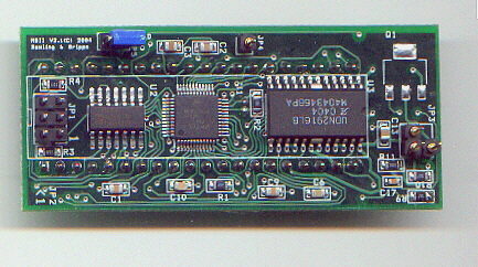
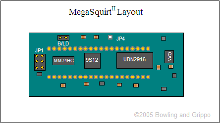
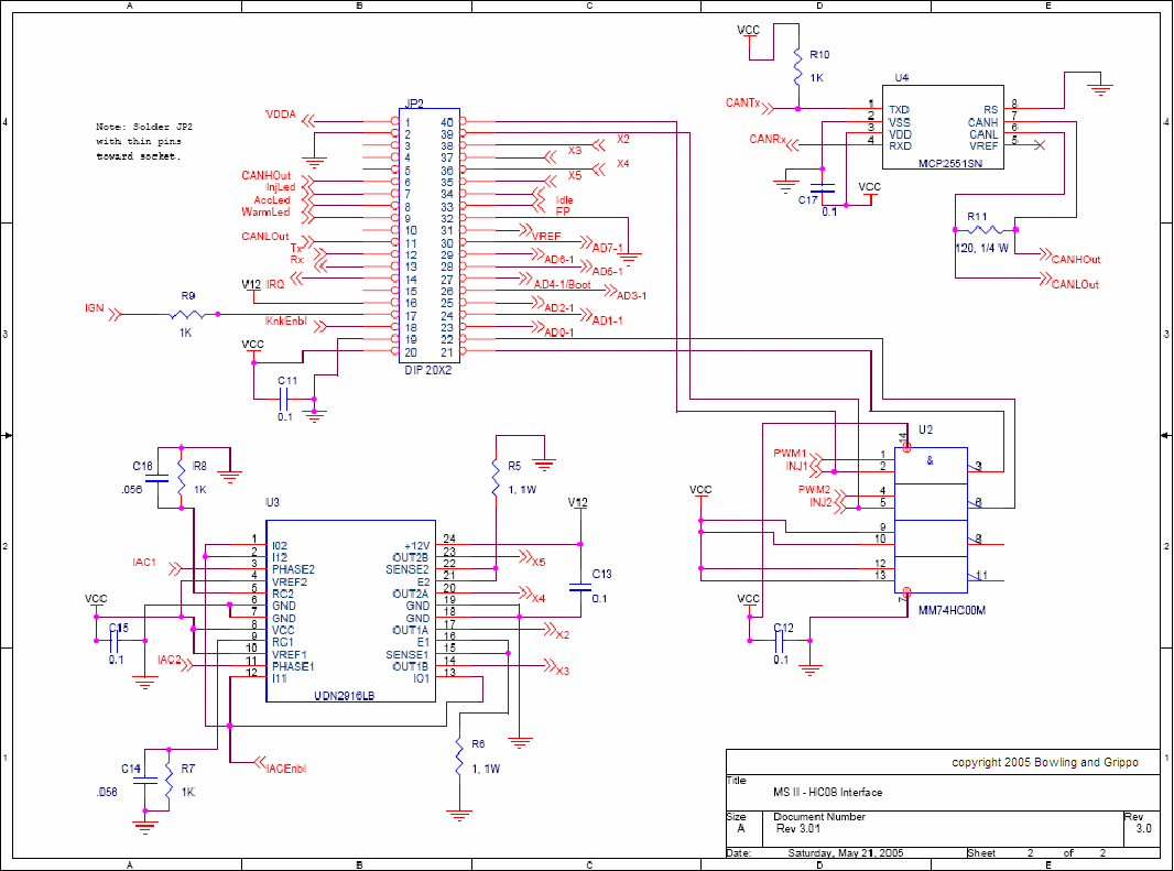
MegaSquirt-II Schematics, Components, and Board Layout
BDM - The processor incorporates a debugging unit that can halt the main processor, read/modify/write memory/registers, restart the processor. The BDM board connects the CPU board to the parallel port of your PC so that the PC can download programs into the flash memory, debug the program...
The PCB is a single, four layer (two signal layers, a power layer, and a ground layer) board. The extra power and ground layers provide noise immunity in the harsh automotive environment.
Here are the MegaSquirt-II schematics for the V2 (blue PCB) (C64 w/ CAN) MegaSquirt-IIs:
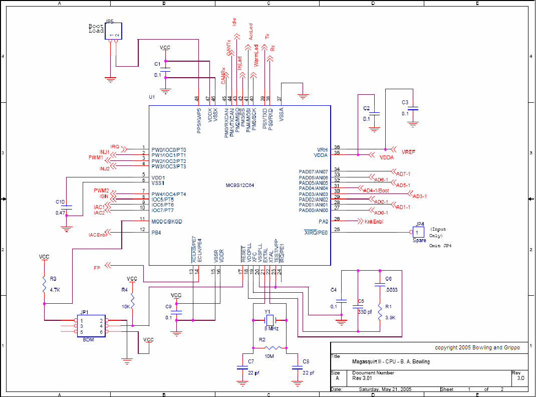
Bootloader
This section explains the bootloader options which are available on the MC9S12C32:
1) The 9S12C32, when it comes from the factory, has a section of flash programmed with a LRE code - this stands for "Load RAM and Execute". At reset on a unprogrammed device, the SCI (and CAN module) will try to communicate with an external host which will allow the upload of user code into RAM, followed by execution of this code. It is very similar to the bootloader used in the HC11. The user has to provide the RAM code to be uploaded (i.e. a routine which grabs S-records and burns flash). For more info, see application note AN2546:
Here is the Product Change Notification (PCN) for the MC9S12C32 indicating that this bootloader code will be programmed in factory silicon:
2) There is a much more elaborate bootloader available for the C32 (compared to the one implemented in the HC08) - see appnote AN2548:
This bootloader not only allows the upload of new code via the serial port, it also allows debug access to accor via. the serial link. In other words, code development and debug can occur over the serial port without the use of a BDM cable.
What all this means is that a factory fresh MC9S12C32 can be programmed using the serial interface (without BDM), first by using the LRE function and burning flash with the serial bootloader in (2), then using the serial bootloader to upload the final application. In addition, the bootloader can be used as a debugger for the EFI code, and even invoke the on-chip breakpoint module and trace.
MM74HC00M Quad 2-Input NAND Gate
In the basic MegaSquirt® configuration, there is an overall 0.1 millisecond timer interrupt (i.e. the MegaSquirt® codes breaks normal execution flow and jumps to interrupt code every 0.1 milliseconds) which is used to control the actual injector pulse width. But for pulse width modulation applications, the timer channel itself (which are connected to the FI outputs) generates the pulse width modulation - this is an approx. 17 KHz frequency with the duty cycle set to control average current. Note that when the injector first opens there is a period of time where full current is applied (a.k.a. peak open time), then it switches over to pulse width modulation current limit for the duration of the FI pulse. This switch-over is handled by the 0.1 ms timer interrupt, as is the overall FI pulse - hence the FI resolution of 0.1 ms.
In the hi-res MegaSquirt® code, the injector open time is controlled directly by the timer at a resolution of 1 microsecond (using a mode known as output compare, which is a hardware operation). But since the timer is in output compare mode, it cannot perform pulse width modulation.
The result is that with the 68HC908 on a standard MegaSquirt® EFI Controller, we can have high resolution, or PWM, but not both.
The NAND gate in the MegaSquirt-II setup gives the best of both worlds. The actual fuel injector pulse is controlled by a timer channel in output compare mode, yielding a 1 microsecond pulse width resolution and a 65 millisecond maximum fuel injector pulse length. The output compare timer channel feeds one input of the NAND gate.
For pulse width modulation current limit, another independent timer channel, set up for pulse width modulation operation, feeds the other NAND gate input. Initially, the pulse width modulation is set to 100% duty (i.e. the input is high). When the FI pulse is initiated by the output compare timer channel, the other input of the NAND gate goes high. With both inputs high, the output of the NAND gate is low - and since the FET driver is inverting logic itself, the two inversions cancel and the FET is turned on. After the period of time (the overall 0.1ms timer loop) exceeds the FI peak time the pulse width modulation duty cycle is switched to a hold current duty value - this toggles the pulse width modulation NAND gate input on/off, which in turns toggles the output. To complete the FI pulse, the output compare timer channel eventually matches (i.e. the FI pulse is complete) and this timer channel goes low - this drives the FET off.
Note for those not familiar with NAND gate operation, the output of a NAND gate is high, unless if both inputs are high which makes the output low. Since the FET driver is another inverter, the overall circuit operating the FET is a AND gate (i.e. both inputs high yields a high output, otherwise it is always low).
The MM74HC00 NAND gate utilizes advanced silicon-gate CMOS technology to achieve operating speeds similar to LS-TTL gates with the low power consumption of standard CMOS integrated circuits. All gates have buffered outputs.
Features:
All devices have high noise immunity and the ability to drive 10 LS-TTL loads. All inputs are protected from damage due to static discharge by internal diode clamps to VCC and ground.
UDN2916LB Dual Full-Bridge PWM Motor Driver
The UDN2916LB stepper motor driver is designed to drive both windings of a bipolar idle air control (IAC) stepper motor. Both bridges are capable of sustaining 45 Volts and include internal pulse width modulation (PWM) control of the output current to 750 milliAmps. The outputs have been optimized for a low output saturation voltage drop (less than 1.8 V total source plus sink at 500 milliAmps).
Features:
The UDN2916LB comes in a 24 lead, SOIC package.
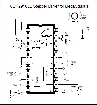
For PWM current control, the maximum output current is determined by the user's selection of a reference voltage and sensing resistor. Two logic-level inputs select output current limits of 0, 33, 67, or 100% of the maximum level. A PHASE input to each bridge determines load current direction. The bridges include both ground clamp and flyback diodes for protection against inductive transients. Internally generated delays prevent cross-over currents when switching current direction. Special power-up sequencing is not required. Thermal protection circuitry disables the outputs if the chip temperature exceeds safe operating limits.
Here is a tutorial on the 2916 circuit.
First, the DC coil resistance of the GM stepper motor (either coil) is roughly 50 ohms. Applying 12 volts to a winding and waiting for a while for the winding to current saturate will yield: 12volts/50 ohms = 0.24 amps. Scales with voltage, but even 20 volts gives approx 0.4 amps saturation current.
Next, the 2916 current limit circuit:
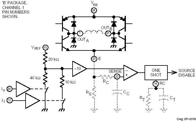
The lower part of the circuit is the overcurrent protection. Io and I1 are both active (low in this case) when the stepper is enabled by MS-II. This gives a current trip threshold point equal to: Vref/(10*Rs). For the MS-II™ circuit, Vref = 5.0 volts and Rs = 1 ohm. So with our values we get 5/10 = 0.5 amps.
What this means is that the stepper motor current must be greater than 0.5 amps before the PWM current circuit kicks in. So it appears that with a GM stepper the most current draw is under 0.4 amps at 20 volts, this is lower than the 0.5 trip threshold point. So the PWM circuit should never activate.
But, in reality, there are things that can cause the PWM circuit to kick in. Long wires, winding flyback pulses, noise during the off time, etc. can cause a instantaneous voltage spike which can trip off the PWM circuit.
In the circuit there are Rc and Cc components. In MegaSquirt-II they are not there (i.e. Cc is 0 and Rc = 0 ohms). These components can be introduced in the circuit to help filter out short spikes. MegaSquirt-II did not use these values because they need to be tuned to a specific situation, depending on wire lengths, routing, etc. Wrong values can cause instabilities and even oscillation. The PWM is called a modified hysteretic oscillator, what it does is when the coil current exceeds the trip point it turns off current for a period of time governed by the product of Rt and Ct, then the current is reapplied. During the off time the current decays below the trip point.
If the situation comes up where the PWM circuit gets triggered, what we have been advising is to jumper out the 1 ohm Rs resistor. What this does is disable the PWM overcurrent detection. What occurs with the jumper Rs the resistance goes to zero, so there is no voltage generated across it and the sense terminal stays at 0 volts. So the current trip point cannot be reached. With Rs jumpered there is no current limiting for short circuit situations - be aware about loose wires shorting to ground, this can take out the chip. If we were to design the stepper circuit again, we would remove Rs and short this out, and use polyfuse protection on the stepper leads. Hysteretic current limit is nice when there is a nice controlled environment with the same stepper motor/wire lengths/routing/etc.
The datasheet alludes to a Rt minimum range of 20K, even though this is not a hard definition in the electrical specification (only a test condition). Early datasheets did not define this Rt range. Note that the time that the current is disabled is governed by the RC product. In our case, Rt is 1K and Ct is 0.056µf, this gives a RC time constant of 56 µsec. The test specification values were 820pf and 56K, which gives 45 µsec, very close to the MS2 RC time constant. The only potential issue is if the RC current source point is loaded down with the 1K resistor. In this case the charge time of Ct would be extended, meaning that the stepper current is turned off longer than 56usec. A test with a known inductive load that would trip the overcurrent and a scope showed the Toff time and it is very close to 60 usec.
The thing to note is if the Rs resistor is jumpered then the Rt and Ct do not come into play because the current trip point is never reached.