Your MegaSquirt-II™ controller has a few options for controlling idle speed. These fall into the broad categories of stepper motor IAC, and Fast Idle valves (PWM or on/off). The stepper type is covered first in this document, the on/off and PWM are covered towards the end of this page (click here).
Your MegaSquirt-II™ controller can control an Idle Air Controller (IAC) to adjust the amount of air entering the intake manifold based on the engine's coolant temperature. The number of IAC "steps" is user set in a 10 element coolant temperature table. With IAC control, your MegaSquirt-II™ controller can be tuned to adjust the engine speed at crank, starting, warm-up, and running conditions, preventing stalling and lowering emissions.
The code works as follows:
You can hold the motor and enclosure and view the pintle closing on the seat. When you have the full range, increase it by a few % and use this as IACStart. This will guarantee the motor always fully opens, regardless of what position it starts out at, but you don't want to make the number so large that the motor keeps spinning a long time on its fully opened stop position.
IACStart does not need to be exact. If a motor moves say exactly 100 steps to go from completely open to completely closed, then you make IACStart say 110, and this is what you also specify in the table of steps vs. coolant temperature.
Then at startup the motor will move to open (step=0), then immediately after go to whatever position is right based on the coolant temperature, say step = 50. This will all take place in about a second, probably before the engine ever fires. Then the motor will slowly move to the closed position as the coolant gets hot, which can be 110 if that is what is in your table of step vs. coolant temperature.
But in fact it will be closed when it reaches step 100, but this is just a tuning issue, you can adjust the steps in the table however you like. If the idle is too fast when you reach temperature, just increase the number of steps in the table. If this does no good, then it means the motor is truly closed and you have to back off the throttle plates.
The number of steps to go from fully open to closed is a user input, from 1 to 255 steps, although it can be made larger than that if needed. As far as the significance of what a position means in steps, that can be displayed to the user in whatever manner we want to put into the display programs - just like the raw TPS voltage can be converted to a % of throttle open.
General Motors idle-air-control (IAC) valves are used on both throttle body and multi-port fuel-injected engines to regulate idle speed. GM has also made a stepper controlled Idle Speed Controller (ISC) for some carbureted vehicles that adjusted the throttle stop position. Chrysler calls their idle air system an automatic-idle-speed (AIS) motor, while Ford refers to it as a throttle air bypass solenoid (AIR B). Other manufacturers may have other, though similar, names for the stepper controlled idle air bypass system.
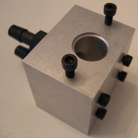
Note: If your throttle body doesn't incorporate an IAC, you can retrofit Richard's (of DarkStar Media) remote IAC. DIY AutoTune sells this Custom Idle Air Control Body for use with Jeep 4.0l IAC Valve. It is a custom machined aluminum IAC body for installing a IAC valve from a Jeep 4.0l motor, perfect for idle control with the your MegaSquirt-II™ controller. You just add the O-ring style IAC valve with and wire it up. 4 Mounting holes on the bottom/side depending on how you mount it with screws included.
The TBI and EFI systems used by General Motors and Chrysler by the late '80s used computer driven, four-pin stepper motors. These motors can be operated through ~256 'steps'. The GM IAC, for example, can turn up to 320 steps. The stepper motor drives a pintle valve to control the amount of air bypassing the throttle plates.
The pintle valve is on a worm gear, rotation of the stepper motor moves it in and out. The coils take turns to rotate the pintle by 90°. At any time, one coil is 'enabled' and can rotate the pintle in either direction, the other coil is in a neutral position (will not cause the pintle to rotate). Applying a voltage to Coil A will turn the pintle 90° in one direction. (The opposite polarity (on coil A) will turn it in the opposite direction.) Applying a voltage to coil B will rotate the stepper motor in the opposite direction by 90°, or back to the original position.
To make the idle speed increase, your MegaSquirt-II™ controller moves the pintle away from its seat. This allows more air to enter into the engine. Likewise, to decrease the idle speed, the pintle is moved closer to its seat.
Note: Beginning in 1985, Ford multi-port EFI uses an Idle Air Control (IAC) valve, which allows air to bypass the throttle plates. Unlike the stepper motors used by GM and Chrysler, the Ford units only have two terminals and one winding. These units regulate IAC plunger position using pulse width modulation (PWM). The idle speed is controlled by applying varying duty cycle percentages.
MegaSquirt-II™ controller code uses coolant temperature as the only input to adjust the stepper IAC.
General Motors EFI engines typically have 4-wire, 56 Ohm stepper motors. (The measured DC resistance can be ~35-45 Ohms). Two GM style motors are available. On type screws into the throttle body as a unit. The screw-in type IAC has a M20 x 1.5 thread with a square, 4 pin connector. One example of an application for the screw-in IAC is a 1984 Corvette.
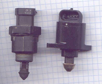
The O-ring style, bolt-on style GM IAC motor uses an 'in-line' 4 pin connector. It is attached to the throttle body with two small machine screws. It was used in 1992 Pontiac Grand Prix SE 3.1L V6, among many other applications.
| Type | Supplier | IAC | Connector |
| Screw-in | Standard Motor Products | AC2 (~$50) | S555 (~$10) |
| Screw-in | AC Delco | 217-406 (~$100) | PT127 (~$26) |
| O-ring | AC Delco | 217-419 (~$60) | PT757 (~$25) |
For the connector (~$13), try:
If your throttle body does not have provisions for an IAC stepper motor, Electromotive offers two billet aluminum IAC motor bodies that accept the threaded motor. One body provides two hose barbs so air can be plumbed with hoses to both sides of your air door. The other body is to be wrapped in an air filter and connected downstream of the throttle with one hose. General Motors throttle bodies often have a separate mount housing for the IAC that could be adapted as well.
Modern IACs are generally a form of stepper motor. Stepper motors are found widely in modern electronics, such as in printers and scanners, etc.
Stepping motors come in two varieties, permanent magnet and variable reluctance (there are also hybrid motors, which are indistinguishable from permanent magnet motors from your MegaSquirt-II™ controller's point of view). Lacking a label on the motor, you can generally tell the two apart by feel when no power is applied. Permanent magnet motors tend to "cog" as you twist the rotor with your fingers, while variable reluctance motors almost spin freely (although they may cog slightly because of residual magnetization in the rotor). You can also distinguish between the two varieties with an ohmmeter. Variable reluctance motors usually have three (sometimes four) windings, with a common return, while permanent magnet motors usually have two independent windings, with or without center taps. Center-tapped windings are used in unipolar permanent magnet motors.
There are a variety of stepper motor types in use in OEM IAC systems. General Motors uses bi-polar, some Chryslers use unipolar, others use PWM proportional control, etc.
For both permanent magnet and variable reluctance stepping motors, if just one winding of the motor is energized, the rotor (under no load) will snap to a fixed angle and then hold that angle until the torque exceeds the holding torque of the motor, at which point, the rotor will turn, trying to hold at each successive equilibrium point.
Unipolar stepping motors (5 or 6 wire) are usually wired as shown in the schematic below, with a center tap on each of two windings. In use, the center taps of the windings are typically wired to the positive supply, and the two ends of each winding are alternately grounded to reverse the direction of the field provided by that winding.
Typical bipolar steppers have 4 leads, connected to two isolated coils in the motor. These are the most common in automotive applications. Bipolar permanent magnet and hybrid motors are constructed with exactly the same mechanism as is used on unipolar motors, but the two windings are wired more simply, with no center taps. Thus, the motor is simpler but the drive circuitry needed to reverse the polarity of each pair of motor poles is more complex.
A bipolar stepper motor has two coils. The leads to both coils are brought out to the harness with 4 wires. If you energize one coil the rotor will rotate to a position aligned with that coil. If you energize the second coil the rotor will rotate a little bit to be aligned between the two coils. If you turn off the first coil the rotor will rotate a little more to line up directly with the second coil. If you energize the first coil again with the opposite polarity of the first time the rotor will rotate a little more, and so on. Your MegaSquirt-II™ controller applies pulses in a particular sequence to the four wires to produce rotation. Each pulse results in specific amount of rotation of the motor . The motor can be made to spin either direction by changing the polarity of the pulses.
On GM IAC steppers, the one coil usually has blue wires leading to it, the other coil has green wires. The schematic below shows how such a motor is wired.
The drive circuitry for such a motor requires a separate H-bridge control circuit for each winding. An H-bridge allows the polarity of the power applied to each end of each winding to be controlled independently. The control sequences for single stepping such a motor are shown below, using + and - symbols to indicate the polarity of the power applied to each motor terminal:
Bipolar permanent magnet stepping motors have no center taps on their windings. Therefore, to reverse the direction of the field produced by a motor winding, we need to reverse the current through the winding. We could use a double-pole double throw switch to do this electro-mechanically; the electronic equivalent of such a switch is called an H-bridge and is outlined below:
ICs specifically designed to drive bipolar steppers are available. Your MegaSquirt-II™ controller uses the UDN2916LB stepper motor driver to drive both windings of a bipolar IAC stepper motor. One problem with the basic (transistor) H-bridge circuit is that with a certain combination of input values (both '1's) the result is that the power supply feeding the motor becomes shorted by the transistors. This could cause a situation where the transistors and/or power supply may be destroyed. A small XOR logic circuit can be added to keep both inputs from being seen as '1's by the transistors.
A characteristic of H-bridge circuits is that they have electrical "brakes" that can be applied to slow or even stop the motor from spinning freely when not moving under control by the driver circuit. This is accomplished by essentially shorting the coil(s) of the motor together, causing any voltage produced in the coils by during rotation to "fold back" on itself and make the shaft difficult to turn. The faster the shaft is made to turn, the more the electrical "brakes" tighten.
To tune the idle air, the MegaSquirt® code allows you to edit the following parameters with the tuning software:
So, for example, if the motor last moved at 140°F, and the hysteresis is set to 5°F, then it won't move again until the temperature reaches 145°F. The setting prevent from moving the motor back and forth constantly, heating it unnecessarily.
A value from 5°F to 10°F is good for most installations. This input can be used to avoid continuous motor motion (and wear) for small coolant temperature changes and random 'jitter' in the coolant temperature signal . Changes to the motor are only made when new coolant temperature > coolant temperature on the last move, or, new coolant temperature < (coolant temperature on the last move - Hysteresis temperature). What this does is allow constant motor motion while the coolant temperature is rising, but when it peaks, there will be no further motion unless things cool back down - which is unlikely.
There are details on how to set these parameters on the MS-II configuration page.
DO NOT set the spare port settings for PT6/PT7 if using an IAC stepper! That is, leave the 'enabled' check box un-checked. The settings for these spare ports are used only if you are not using an IAC stepper motor. Enabling them will disable the stepper motor function and your IAC will not work.
To wire a bipolar stepper motor to your MegaSquirt-II™ controller on a V2.2 main board, on the MegaSquirt® PCB you connect jumpers that connect the IAC pins for the your MegaSquirt-II™ controller daughter card to the DB37 connector, then to the IAC. For example, for a 'square connector' style GM IAC, you connect:
If you are using the relay board, and have connected the wires for the IAC to DB37 pins 25, 27, 29, and 31, then:
(Note that the same DB37 pins are used for stepper IAC control with V2.2 and V3.0 main boards.)
Note that the square and in-line steppers have different connections (below).
Note that if you have the wiring connected incorrectly (or if you don't know how to wire it because it is an undocumented type), wire it up as best you can. Note that you will be able to tell which two wires connect to the same coil by the resistance across those two wires - it will be about 30 to 50 Ohms if they are on the same coil, infinite otherwise. Then try the IAC. One of two things will happen:
If you have the IAC out of the throttle body for testing, you might accidentally eject the pintle from the IAC. If you do so, simply screw it back it place by inserting it into the housing and using a gentle pressure as you screw it all the way in (generally you turn it clockwise, like a screw, to turn it in).
Then you need to select the 'Idle Control/Algorithm' in TunerStudioMS. In some cases setting the stepper motor to "IAC Stepper Always On" will cause the IAC to get hot. However setting it to "IAC Stepper Moving Only", might cause a problem with idle speed changing from one start to another.
You can test if your IAC is suitable for 'always on' by leaving your stepper powered on the bench for 15 min or so. If it doesn't feel too hot to you, then set it to "Always On". Apparently this is what GM does. But if you want to be safe they should test it on the bench for 15 min or so, or monitor it closely in the car while not moving for at least 15 minutes, checking the IAC temperature frequently with your fingers. It may get warm, but it shouldn't burn your fingers just touching it.
When you have the IAC installed in your car, you might need to adjust the 'Time Step Size (ms)' under 'Idle Control'. The default is 2.5, however, you might need to use up to 6.0 or even more, depending on your particular stepper. This allows for a slower reacting stepper, but also slows the response time, and increases the heat in the stepper motor. So keep it as low as you can, while still having reliable operation. More of the stepper settings are described here.
For some IAC stepper motors, you might need to make some adjustments because the power resistor values may not be quite low enough for your application. This could cause sporadic problems. To see if this is the problem, cut the leads off a resistor or use a small piece of wire and solder it across the two power resistors on the bottom of the your MegaSquirt-II™ controller board. (That is, jumper each resistor separately, don't jumper one resistor to the other resistor.) These are the two large brown units on the BOTTOM of the board, on the end opposite the side of the board with the 2x3 pin header (typically they are marked 1R0). These have large solder pads on each side - just jumper across each one so you get 0 Ohms across the resistors and see if this improves operation. If it does, leave the resistors and jumpers in place. This is very likely to be the problem for those who see the proper step commands given in software but inconsistent response from the motor, such as requiring a restart to lower the hot rpm after a cold start.
The resistors are for protection against shorted wiring. If you short the wiring to your stepper motor you could burn out the stepper chip, as you could many other devices on a car by shorting them. But they are not needed for normal operation and will not reduce the longevity of your stepper motor or of the chip. We looked at this problem a while back and found it to be due to transient spikes that caused the chip to shutdown even though there was no over-current. To eliminate it you need to add a filter circuit to it and tune the circuit for your particular setup using a scope. But we don't feel this additional complexity is worthwhile or necessary.
Also, make sure you have a good 12V supply to your MegaSquirt® EFI Controller, and to MS-II™ (the S12C to JS9 (+12C) jumper), so that it isn't compromised anywhere along the path.
In addition to jumpering the 1 ohm power resistors, another modification you might try to fix inconsistent operation is to add a 100 µF/25V capacitor between the +12 V line to the stepper chip and ground. If there is still a problem, keep going up in capacitance value, up to 1000 µf. If the 100 µf capacitor completely solves the problem, then you can try going down to 50 or 10 µf. The cap is maintaining current to the stepper in case of the current dropping during cranking. You want the added capacitor to be as close to the stepper chip as possible - not down on the V3 board. The most practical place is at the 40 pin socket where you put the +12V supply.
Instead of using a stepper motor based Idle Air Control valve, your MegaSquirt-II™ controller can be configured for a 'Fast Idle Valve'. The fast idle valve is an open/close solenoid vacuum control valve to admit more air to the intake manifold when cold. Unlike a cold start injector, it does not handle fuel at all, only additional air. The fast idle solenoid is not the same as an IAC motor, or anything that is controlled like a stepper motor. It is either open or closed. The fast idle solenoid is an off/on electrically controlled vacuum “leak” that speeds the engine RPM for cold starts. Such solenoids have been used often in modern cars, frequently to control EGR valves. The fast idle solenoid takes clean air from the air cleaner and allows it to bypass the throttle and go directly into the intake manifold. This does not cause a lean condition [as it would with a carburetor] since the MAP sensor adjusts for the “extra” air. SDS sells a air bypass valve which you could use for a fast idle solenoid. The price is ~$70.00 - look for "fast idle solenoid" on their specifications page. However, the "Fast Idle Solenoid" that SDS sells appears to be the same thing as the "Solenoid-actuated 3-Port Fuel Tank Selector Valve" that J.C. Whitney sells for half that price
under P/N 81ZX2686W. There are some possibilities for the fast idle solenoid from the NAPA catalog: 2-2307 EGR Solenoid (91-93 Buick, 88-93 Chevy) $28.19 2-2109 Bowl Vent Solenoid (78-86 Ford 2bbl) $47.89 (Ford CX-239) These all have separate inlet/outlet that looked usable for rubber hose connection. You may be able to get one at a wrecking yard.
There also may be an idle speed screw in the throttle body that is blocked by a small metal plug. Remove that plug and you will see a conventional idle speed screw. It is easier to make fine adjustments in the field with this screw than it is with the IAC.
Note that if you are using a PWM Idle valve, such as those used in some Ford products, the standard transistor on a V3 main board is not sufficient to power the valve directly (on a V3.57 SMD main board, or a MicroSquirt, the FIlde transistor *IS* sufficient to drive a PWM idle valve without modifications). On a V3 main board, you need to:
To configure the software for the PWM FIdle valve warm-up engine speed control:
You have to discover the proper PWM settings for your idle valve. You can do this by trial and error, research (factory service manual or internet), or by finding someone on the forums who has the same idle valve as you. For example, the Ford PWM idle valves typically used with EDIS run best at a frequency of around 300-320 Hz.
If you are using PWM Idle control, you cannot use the FIdle relay on the relay board, and have to jumper the relay socket. The jumper goes from the relay socket hole nearest the CB1 polyfuse to the relay socket hole nearest DB37 pin #4.
You have to discover the proper settings for your idle valve. You can do this by trial and error, research (factory service manual or internet), or by finding someone on the forums who has the same idle valve as you.
To find appropriate settings, you might try Idle PWM values of 25%, 50% and 75% in quick succession while the engine is relatively warm and running (That is, type them into the green highlighted row of the table and see what happens to the rpm). Then you should see very quickly which way opens the valve (higher rpm) and which way closes it (lower rpm). That should establish the 'direction' of the valve with respect to the processor output. It may be a little tricky if the engine wants to stall (or warms up very quickly), but you are mostly looking at the overall effect. If you can't keep the engine running, you might have to use the throttle stop to increase the engine rpm temporarily while doing these tests.
If the engine rpm doesn't change with changing PWM%, you need to check the software settings (make sure you have selected 'PWM Warm-Up' under 'Fuel Set-Up/Idle Control' and that you are not using the FIdle pin as a spare port), idle valve, the wiring, and MegaSquirt itself to find out why. A stim can be helpful for checking MegaSquirt, the idle LED should change brightness with changing PWM%.
You might also check if the 75% value made any difference in engine rpm over the 50% value. If it did make a difference to engine rpm, then try 80%, 85%, 90%, etc. to see at which value increasing the PWM% made no difference to the engine rpm. That would become your maximum Idle PWM% value. If 75% did not make any difference over 50%, then try 70%, 65%, etc. to see what the maximum value is.
Suppose from this you find that the engine rpm is increased at 75% over 50%, and engine rpm is higher at 50% than at 25%. Then you know that the valve open with increasing PWM%. Suppose you then do the next test an find that the rpm stops increasing at 90% (i.e. no faster than at 85%). Then your PWM Idle PWM curve should start at 85%, and end at 0% when fully warmed up (and note that you set your fully warmed up rpm with the physical throttle stop, not the idle PWM% software setting.)
Then tuning the PWM% is just a matter of doing a cold start, and adjusting the PWM% from the 85% value is a smoothly decreasing fashion to 0% percent at the temperature you consider fully warmed up. The best way to do this is to let the vehicle cool-down over night (you only get one cold-start a day), then start the vehicle, and while idling in the driveway adjust the PWM% values so the engine runs best (smoothest while not unacceptably high for you) in each bin as it warms up.
It may take a few tries to get it right (partly because the interpolation between bins can throw things off a bit at first - this is where it helps to have entered a smoothly decreasing set of values from the start).
Once that is done, you might have to slightly re-tune your warm-up enrichments from a cold start to be optimal.
MegaSquirt® and MicroSquirt® controllers are experimental devices intended for educational purposes.
MegaSquirt® and MicroSquirt® controllers are not for sale or use on pollution controlled vehicles. Check the laws that apply in your locality to determine if using a MegaSquirt® or MicroSquirt® controller is legal for your application.
©2004, 2011 Bruce Bowling and Al Grippo. All rights reserved. MegaSquirt® and MicroSquirt® are registered trademarks. This document is solely for the support of MegaSquirt® boards from Bowling and Grippo.