Click here for MegaSquirt® MegaManual™ Information, Guides, and Links
Users who want custom crank wheels for missing tooth applications (either direct decoder with MS-II or 36-1 for EDIS) can have custom wheels made at a number of places.
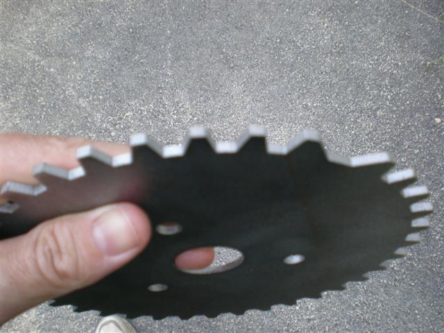
As an example, Bruce has made up a custom 36-1 missing tooth crank wheel for a small block Chevrolet. Here are photos (the tooth edge one is somewhat blurry):

It is very easy to make, just 10 minutes with AutoCAD Light 97 and emailing the .DXF file to Waterjet Cutting Service in Lynchburg, Virginia:
(Note that the latest version of AutoCad Light 2008 is $800 - you may wish to investigate alternatives that are compatible with the .DWG/.DXF formats.)
The cost for 1/8 inch mild steel stock (0.125" = 3mm, must use a ferrous material as it must be magnetic) for 7.5 inch teeth tip diameter was US$60.00 for two wheels. They arrived in the mail two weeks later - and they did a superb job! No touch up at all required, it is ready to bolt-on and use.
Drawing up the wheel in AutoCAD took 10 minutes. The only AutoCAD commands Bruce invoked were the following:
Bruce made the teeth tip match up with the sensor tip width. He is using a Magnetti-Marelli VR sensor (commonly available on eBay) and this has a ~0.175 inch (~4.5 mm) sensing element diameter.
Note also that best bet is to obtain an OEM matched wheel and sensor set whenever possible. If the wheel won't fit, by all means make your own wheel, but with the exact same tooth type, so you know it will be matched to the sensor. Don't just grab a Ford sensor and a Honda wheel and expect them to work with each other.
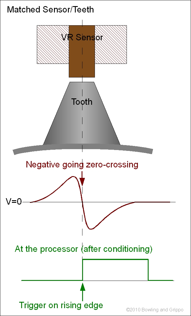
The most important consideration for a VR sensor is that the tooth width (not the wheel thickness, but the length of the top of tooth in the direction of travel) should be matched to the sensor tip width (not the overall all width of the sensor, just the sensing element which is usually visible at the end). The correct width will help provide a sharp zero-crossing transition, making the timing predictable.
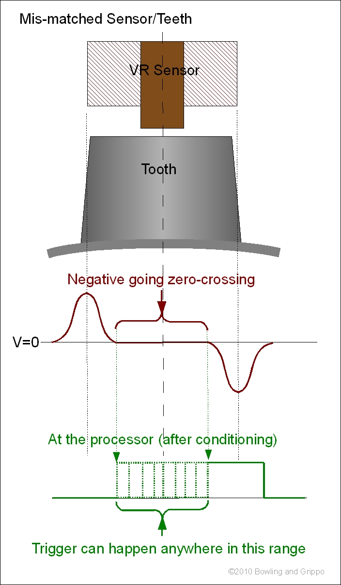
A tooth that is too long will 'spread out' the zero crossing, making the zero-crossing unpredictable, causing timing 'jitter'.
Note that there is a slight possibility of the opposite situation - the sensor being much wider than the teeth. This may happen if you try to put a wheel with many teeth into a distributor, for example. Too wide a sensor is not good, as the signal will be weak, subject to noise, and likely unusable. If the sensor approaches the width of a tooth plus the gap, the signal will be lost altogether (except for the missing tooth).
Without doing a lot of testing, the safest assumption is that the ideal tooth is a right triangle shape with the tip just slightly blunted (to about 1/8" or 3mm on the flats to match the VR sensor tip width) by a lathe to make it a little safer and true it all up. The right triangle provides a slow up ramp, then the right angle side provides a very sharp vertical drop - which is what you want to minimize the crossing location error.
The spacing between the sensor tip and tooth is important. The VR sensor output voltage output is highly dependent on the proximity of the tooth.
The tooth shape Bruce choose was more experimental, especially the missing one with the shallower slope of the trailing/leading edge. Using a rectangular/square tooth works, too, and is easier to generate.
For the VR sensor, you can adapt an OEM sensor (like the ford EDIS sensor), or Google the AI-TEK (formerly Airpax) VR sensors (have a look at 70085-1010-001 or 70085-1010-002)
Here are some really good links on VR sensors and timing wheel tooth geometry:
www.ai-tek.net/pdf/24_PrinciplesofOperation_VR6_2001.pdf
www.ai-tek.net/pdf/25_SensorSelection_6-2001.pdf
archives.sensorsmag.com/articles/0298/mag0298/index.htm
www.integratedsoft.com/papers/techdocs/tech_9mx.pdf
There is more info on variable reluctor crank sensors here: www.megamanual.com//ms2/pickups.htm