Procedure for Configuring Dual Spark Wheel Parameters
Code versions 2.905/3.600 and up incorporate a separate, simpler procedure for setting up the wheel timing. This is called Auto Trigger. You can read about it here: AutoTrigger
This procedure describes how to find the tooth for the first tach pulse and involves determining two inputs: Delay Teeth and Trigger Offset. The other parameters are more clear cut and have been defined elsewhere.
- Turn the wheel with normal direction of rotation until cylinder #1 is at TDC compression. Normally this is where the crank wheel mark lines up with a timing pointer. Put a mark on the wheel that aligns with the tip or center of the VR sensor. This doesn't need to be closer than a few degrees; you can get the timing exact with a timing light later.
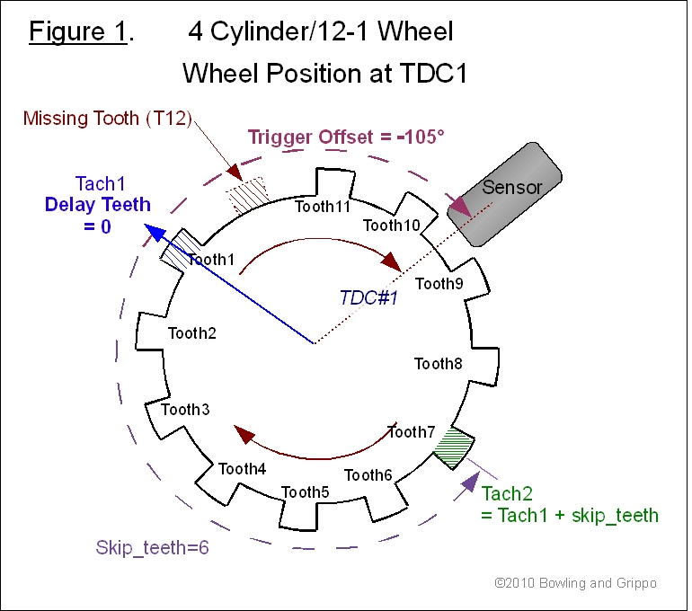
- After step 1, the wheel will look like either Fig 1 or Fig 2, that
is, the missing gap will either not yet have passed the sensor (Fig 1) or
it will have passed it (Fig 2). For the Fig 1 case you want to get to the point where, after rotation in the normal direction, the tooth right after the missing gap sends a trigger to the ECU. If the tooth and sensor are properly sized and matched (more on this later), this trigger will occur when the tip or center of the sensor is over the center of the tooth. This tooth, right after the missing gap, is always numbered T1 and is the tooth at which wheel synch is declared – you can’t declare it any sooner with just an M-N wheel. So rotate the wheel in the normal rotation until this trigger occurs. For Fig 1 you can see that it will take a rotation of about 3.5 teeth to achieve this, and then T1 center will be aligned under the sensor tip and the wheel position will be 3.5T x 30 °/T = -105° ATDC1. What you are trying to do is determine where to start the first tach pulse. By design of the code it has to start AFTER TDC1, and in Fig 1 this has been achieved on tooth 1. So, you can set Delay Teeth = 0 and make Tach 1 be at T1. At this point Tach 1 has a trigger offset of -105° ATDC1.
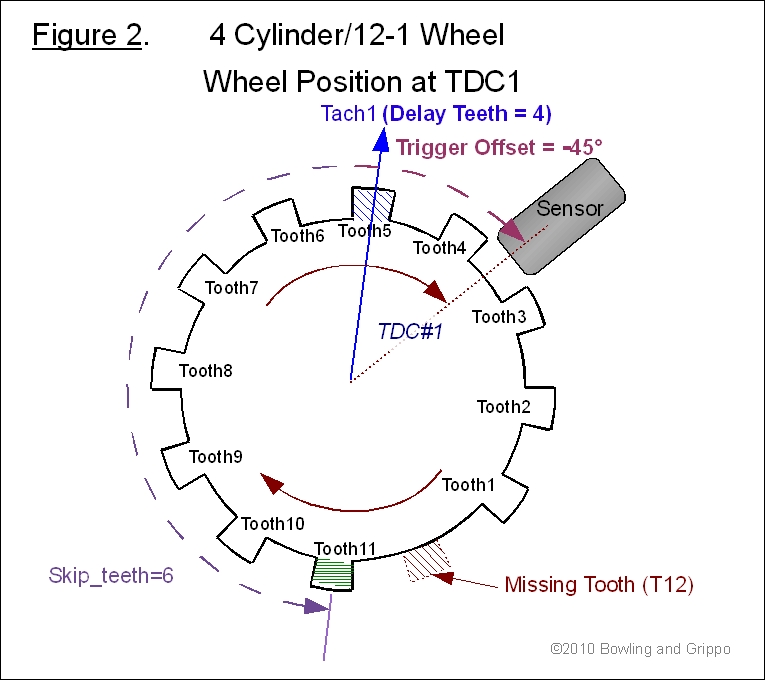
- If the situation is as in Fig 2, then you can see that when tooth T1 was aligned under the sensor centerline (synch), this position was BTDC1, because about 2.5 teeth later is when TDC1 occurs. Since we need to be AFTER TDC to start a tach pulse, we need to delay at least 3 teeth after T1. Let’s use 4 teeth to make it clear in the figure. This will put us on the centerline of T5, about 1.5 teeth ATDC1. So, set Delay Teeth = 4, make Tach 1 be at T5 and trigger offset will be 1. 5T x 30 °/T = -45° ATDC1.
- It is desirable to keep Delay Teeth small so that starting time will be minimal, since there can be no spark calculation until Tach 1 is reached. Fitting the dwell plus spark advance duration within 2 tach cycles is also an even more important consideration here. Hence, in some instances it may be desirable to force another cylinder to be the first, because it may be closer to T1. This is no problem as long as you move the no. 1 ignition output to the coil for this cylinder, and wire all the subsequent outputs to the next coils in their firing order. Also note that for wasted spark you can work with either the compression or exhaust stroke. The procedure for this is the same as steps 1-3 above, except you use TDC for a different cylinder.
- For odd fire engines the same procedure is followed, just as if it were an even-fire engine, except you additionally need to set the Odd Angle (Output 2 Offset) to a positive advance if the second output fires earlier than it would if the engine were even fire, and set to retard (minus advance) if it fires later.
Notes on Wheel Triggering
A wheel produces a signal in a VR or Hall sensor because the shape, speed and proximity of a tooth causes changes in the magnetic field in the sensor, and the sensor output signal is proportional to the rate of this field change.
For a properly sized VR sensor/wheel tooth, with the proper polarity selected, the zero crossing trigger is on the center of the tooth. With the wrong polarity or mismatched sensor/wheel you can't be sure where it will wind up. And what is worse, you can't a priori pick the right edge polarity. So you can do one of three things:
- (Best) Set it up on the bench the way you want to set it up on the car and scope the output. Even then you have to figure out how this will come out when it goes through the VR circuit (and the MS-II™ and MicroSquirt® input circuits are different, to add to the problem). This confusion can be avoided by oscilloscope to observe both the input waveform to the circuit and the output of the circuit that goes to the processor. Then you want to select the polarity of the edge going to the ECU to be that which lines up with the 'most vertical' zero crossing on the VR input side. See the respective schematics for where to probe the circuits.
- (Easiest) Go ahead and set the delay tooth, trigger edge and trigger offset under the assumption that the zero crossing trigger will occur when the centers of the sensor and tooth are aligned and this will be what the ECU sees. Then check the advance with a timing light; if the spark timing is not right, reverse polarity on the wires or the change the trigger edge input.
- Use the tachRef program. This will show what the teeth will look like to the ECU. The wrong polarity will show up as either an extra tooth or erratic spacing of the teeth in the region around the missing tooth section. If polarity is right and the sensor/wheel tooth are matched, you should be able to pick one edge (rising or falling) such that the distances between those edges should all be the same except double(triple) around one (two) missing tooth.
Note also that best bet is to obtain an OEM matched wheel and sensor set whenever possible. If the wheel won't fit, by all means make your own wheel, but with the exact same tooth type, so you know it will be matched to the sensor. Don't just grab a Ford sensor and a Honda wheel, for example, and expect them to work properly with each other. There is more info on crank sensors here: www.megamanual.com//ms2/pickups.htm
In this document, some parameter terminology may be used interchangeable with the code, INI, or tuning interface designations (which are sometimes identical). The equivalent nomenclature is:
| Preferred in this document: | Tuning Software: | Code: | INI: |
| No_Skip_Teeth | Skip Teeth | No_Skip_Teeth | No_Skip_Teeth |
| Delay_Teeth | Delay Teeth | Delay_Teeth | Delay_Teeth |
| SparkFuelOffset | Spark/Fuel Offset | spk_fuel_offset | spark_fuel_offset |
| InjStart | Injection Timing Delay | InjStart | InjStart |
| Trigger Offset | Trigger Offset | adv_offset | triggerOffset |
| Odd_Angle | Offset (advance) for Output #2 | OddAng | OddAng |
| →→→ | →→→ |
→→→ | →→→ |
→→→ | →→→→ |
↓↓ Under Construction ↓↓ |
←←← | ←←← |
←←← | ←←← |
←←← | ←←← |
©2010 Al Grippo and Bruce Bowling and Lance Gardiner - All rights reserved. MegaSquirt® and MicroSquirt® are registered trademarks.