
Megasquirt-II Sequencer™ Wiring
Megasquirt-II Sequencer™ Wiring
There are a number of tools and techniques you will need to wire MS-II Sequencer™ to your vehicle. You will also need some specialized knowledge. We will try to present an overview of everything you need here (if you have questions, ask them on the forums at www.microsquirt.com):
Tools:
Supplies:
Of course you will also need a PC computer to run the tuning software. Any computer that can run Windows 98 or higher (i.e., WinMe, WinXP, WinVista) will work. Ideally the computer will have a serial port (9-pin male connector), but many USB/Serial adapters have been used successfully. A laptop computer is easiest to use in the vehicle, of course, and cheap older laptops with Win98+ and a serial port are commonly available at low cost.
NOTE: The wire labeled "Vref" is the +5V voltage source for the MAP sensor and the TPS sensor. This wire only connects to these components (and possibly the LEDs, if used), so be very careful to not connect this directly to ground or (worse) +12V battery. Bad things will occur if you mis-wire this one - double check your work.
When wiring up a vehicle, we recommend performing this in discrete and deliberate stages - this is how to approach this:
For each circuit, you will need to:
Each of the two AMPseal connectors has 35 pins, numbered in rows from 1-2, 13-23, and 24 to 35. They are numbers from left to right as viewed looking in to the connector on MS-II Sequencer™. These numbers are also imprinted in the connector itself, if you look carefully.
You may have to put the harness ends of the wiring looms together by inserting the wires into the connector, etc.. The best instructions are Ampseal's, which you can read in a PDF file here: A35_harness_assemble.pdf.
The two Ampseal connectors are identical. One is at the end of the case marked "RED", the other is at the end of the case marked "GREEN". Most of the inputs and secondary outputs come out the "GREEN" Ampseal connector, and this is wired very similarly to MicroSquirt®. The 8 injector and 8 ignition outputs come out on the "RED" Ampseal connector.
"GREEN" Ampseal:
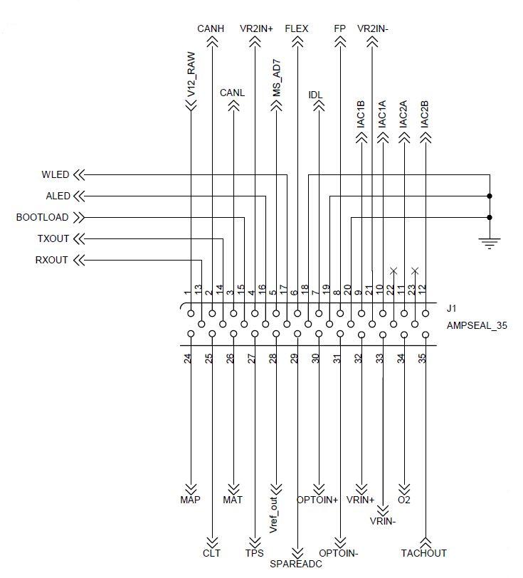
Wiring the "GREEN" Ampseal connector of the MS-II Sequencer™ to the external harness is much the same as with MicroSquirt® (www.microsquirt.info/uswiring.htm). The only difference is that the two injector (INJ1 and INJ2) and ignition (IGN and IGN2) wires on the harness are now the idle IAC stepper outputs. You use the same sensors, etc.
| Pin | Name | Function | Harness Wire Color(s) (main/stripe) DRAFT |
| Pin1 | 12 Volt Supply | This connects to a switched 12 Volt supply. Use the ignition switch to control a relay that provides 12 volts to both the MS-II Sequencer™ and the injectors. | Red |
| Pin2 | CAN High | This is one of two Controller Area Network (CAN) communications lines, used to communicate with MegaSquirt peripherals. | Blue/Yellow |
| Pin3 | CAN Low | This is one of two Controller Area Network (CAN) communications lines, used to communicate with MegaSquirt peripherals. | Blue/Red |
| Pin4 | VRIN2+ | Second ignition input signal (Input 2) for a cam position sensor or second crank sensor with the Dual Spark option. | Brown/White |
| Pin5 | N/C | Not Used | n/a |
| Pin6 | Flex Fuel | For input from a ethanol Flex Fuel sensor. | Purple/White |
| Pin7 | FIDLE | This is the output for controlling an ON/OFF style FIdle or a PWM style IAC (usually found on Fords). You uses either a stepper type IAC, or a FIdle (on/off) or PWM style idle valve. | Green |
| Pin8 | FUEL PUMP | This output controls a fuel pump relay by providing a ground when the fuel pump should be running. It cannot control a fuel pump directly. | Purple |
| Pin9 | IAC 1B | Stepper idle air controller lead for coil 1, pin B. This are typically used on GM applications, among others. See MS-II™ Idle Air Control for more details. | Green |
| Pin10 | IAC 1A | Stepper idle air controller lead for coil 1, pin A. This are typically used on GM applications, among others. See MS-II™ Idle Air Control for more details. | Blue |
| Pin11 | IAC 2A | Stepper idle air controller lead for coil 2, pin A. This are typically used on GM applications, among others. See MS-II™ Idle Air Control for more details. | White/Red |
| Pin12 | IAC 2B | Stepper idle air controller lead for coil 2, pin B. This are typically used on GM applications, among others. See MS-II™ Idle Air Control for more details. | White |
| Pin13 | SERIAL Rx | This pin is used to receive data from the laptop computer serial port (usually a DB9 or DB25). It is connected to Pin3 on a DB9 connector (Pin2 on a DB25) to plug into your laptop/notebook computer. | Red (pre-wired to jack) |
| Pin14 | SERIAL Tx | This pin is used to receive data from the laptop computer serial port (usually a DB9 or DB25). It is connected to Pin2 on a DB9 connector (Pin3 on a DB25) to plug into your laptop/notebook computer. | Orange (pre-wired to jack) |
| Pin15 | BOOTLOADER | This pin is grounded to enter bootloader mode, which allows you to update the embedded code in MS-II Sequencer™'s "MicroSquirt®" processor. This is the processor that uses the standard code shared with MS-II™ and MicroSquirt®. You can connect this lead to a switch, with the other side of the switch connected to ground. When you close the switch and reboot MS-II Sequencer™ EFI controller, you will be in bootloader mode. (On beta units, this lead should be tried to Vref when not actively using the bootloader.) | Purple/Black |
| Pin16 | ACCEL LED | This is the supply for an 'acceleration indicator LED'. You connect the cathode (short lead) of and LED (light emitting diode) to this wire. The longer lead of the LED you connect to a 330 Ohm resistor, then connect the other side of the resistor to the Vref wire (5 Volts). Be certain that Vref will not be grounded or connected to 12 Volts. Or you could use some other voltage source beside Vref. For example, you could use the battery supply voltage (nominally 12 Volts) as long as you increase the current limiting resistor value to 1K Ohms (to keep the current within limits). The LED will then light whenever accel enrichment is in effect. | Yellow/Black |
| Pin17 | WARM-UP LED | This is the supply for an 'warm-up indicator LED'. You connect the cathode (short lead) of and LED (light emitting diode) to this wire. The longer lead of the LED you connect to a 330 Ohm resistor, then connect the other side of the resistor to the Vref wire (5 Volts). Be certain that Vref will not be grounded or connected to 12 Volts. Or you could use some other voltage source beside Vref. For example, you could use the battery supply voltage (nominally 12 Volts) as long as you increase the current limiting resistor value to 1K Ohms (to keep the current within limits). The LED will then light whenever warm-up enrichment is in effect. | Yellow/White |
| Pin18 | N/C (ground) | Not Used | n/a |
| Pin19 | SERIAL GROUND | Serial communications dedicated ground. | Green (pre-wired to jack) |
| Pin20 | SENSOR GROUND | This is a dedicated sensor ground wire. All of the sensor grounds can be connected to this wire to reduce then possibility of electrical noise. | White/Black |
| Pin21 | VR2IN-/GROUND | For early Sequencers™, this is one of several ground wire pins (18 through 23). All of the ground wires should be run to the same spot on the engine (to avoid ground loops). Make sure you have a good ground connection from the batteries negative terminal to the engine, and from the engine to the frame as well.
For later Sequencers™ (v1.04+ produced after August 2010), this wire is the ground for the VR2 circuit. | Black |
| Pin22 | GROUND | This is one of several ground wire pins (18 through 23). All of the ground wires should be run to the same spot on the engine (to avoid ground loops). Make sure you have a good ground connection from the batteries negative terminal to the engine, and from the engine to the frame as well. | Black |
| Pin23 | GROUND | This is one of several ground wire pins (18 through 23). All of the ground wires should be run to the same spot on the engine (to avoid ground loops). Make sure you have a good ground connection from the batteries negative terminal to the engine, and from the engine to the frame as well. | Black |
| Pin24 | MAP | This pin is connected to the output from a MAP sensor that puts out a 0 to 5 Volt signal (roughly) proportional to absolute pressure. General Motors MAP sensors are suitable (Pin24 connects to pin B on the sensor, pin A is grounded, pin C gets 5 Volts from Vref (Pin28 on MS-II Sequencer™)). You can also use the original MPX4250 MAP sensor used with MegaSquirt, you connect the pion #24 to the sensor's Pin1, Pin2 is grounded, and 5 Volts (Vref) is connected to pin#3. | Green/Red |
| Pin25 | CLT | MS-II Sequencer™ uses the coolant temperature to determine the warm-up enrichments. The sensor must be a negative temperature coefficient (meaning the resistance decreases as the temperature increases). Most automotive temperature sensor are this type, however the default sensors are General Motors sensors. | Yellow |
| Pin26 | IAT | MS-II Sequencer™ uses the intake air temperature (aka. manifold air temperature = MAT) to determine the air density for fuel calculations. The sensor must be a negative temperature coefficient (meaning the resistance decreases as the temperature increases). Most automotive temperature sensor are this type, however the default sensors are General Motors sensors. | Orange |
| Pin27 | TPS | This is a pin for the 'sense' connection on a throttle position sensor.
To hook up your throttle position sensor (TPS), disconnect the TPS, and use a digital multi-meter. Switch it to measure resistance. The resistance between two of the connections will stay the same when the throttle is moved. Find those two - one will be the +5 Vref and the other a ground. The third is the sense wire to MegaSquirt. To figure out which wire is the +5 Vref and which is the ground, connect your meter to one of those two connections and the other to the TPS sense connection. If you read a high resistance which gets lower as you open the throttle, then disconnected wire is the one which goes to ground, the other one which had the continuous resistance goes to the +5 Vref from the MegaSquirt, and the remaining wire is the TPS sense wire. | Blue |
| Pin28 | Vref | This is a 5 volt supply for the throttle position sensor and the MAP sensor. DO NOT connect it to 12 Volts! The wire labeled "Vref" is the +5V voltage reference for the MAP sensor and the TPS sensor. This wire only connects to these components, so be very careful to not connect this directly to ground or (worse) +12V battery. Bad things will occur if you mis-wire this one - double check your work. | Gray |
| Pin29 | SPARE ADC | Can be used for external baro MAP sensor. | Orange/Green |
| Pin30 | OPTOIN+ | Square wave ignition signal input positive connection for Input 1. Note that you can use only one of OPTIN+/- or VRIN+/-, because they connect to the same processor pin. For the second ignition input (Input 2), use VR2IN+ (Ampseal pin 4) | Gray/Red |
| Pin31 | OPTOIN- | Square wave ignition signal input negative for Input 1. Note that you can use only one of OPTIN+/- or VRIN+/-, because they connect to the same processor pin. For the second ignition input (Input 2), use VR2IN+ (Ampseal pin 4) | Gray/Black |
| Pin32 | VRIN1+ | Variable reluctor A/C signal input for Input 1. Note that you can use only one of OPTIN+/- or VRIN+/-, because they connect to the same processor pin. For the second ignition input (Input 2), use VR2IN+ (Ampseal pin 4) | Silver (coax center wire) |
| Pin33 | VRIN- | Variable reluctor A/C signal input (ground) for Input 1 & Input 2 (if used). Note that you can use only one of OPTIN+/- or VRIN+/-, because they connect to the same processor pin. For the second ignition input (Input 2), use VR2IN+ (Ampseal pin 4)
For later Sequencers™ (v1.04+ produced after August 2010), this wire is the ground for the VR1 circuit. | Silver (coax shield) |
| Pin34 | O2 | This is connected to the oxygen sensor output wire. This may be a 0 to 1 Volt signal directly from a narrow band sensor, or a 0 to 5 Volt signal from a wide band sensor controller. | Pink |
| Pin35 | TACH OUTPUT | This connection can be used to drive a standard tach (OEM or aftermarket). For details on how to hook it to your tach, see your tach installation manual or OEM service manual. | Green/Yellow |
"RED" Ampseal:

It is critically important to realize that IGNX, INJX, etc. refers to the Xth cylinder in the firing order. For example, on a small block Chevrolet with a firing order of 1-8-4-3-6-5-7-2, IGN4 in connected to cylinder #3 (the fourth cylinder in the firing order). Similarly, INJ6 connects to cylinder 5, and so on.
| Pin | Name | Function | Harness Wire Color(s) (main/stripe) DRAFT |
| Pin 1 | INJ8 | This is the injector GROUND for the cylinder that is 8th in the firing order. For example, with the small Chevrolet firing order of 1-8-4-3-6-5-7-2, this would be the injector ground for cylinder #2 (the front passenger's side cylinder). With a four cylinder and a firing order of 1-3-4-2, this injector driver ground is not used. | not assigned yet |
| Pin 2 | INJ7 | This is the injector GROUND for the cylinder that is 7th in the firing order. For example, with the small Chevrolet firing order of 1-8-4-3-6-5-7-2, this would be the injector ground for cylinder #7 (the back driver's side cylinder). With a four cylinder and a firing order of 1-3-4-2, this injector driver ground is not used. | not assigned yet |
| Pin 3 | GND | Ground wire. Ground to the engine block. On the grounds, you need to tie the high current grounds on the red connector (the one with all of the injector outputs) to the engine block. There is a break in the ground plane layer which separates the high current items (injector drivers, stepper chip, low-side drivers) from the digital and analog side (on the green end). | not assigned yet |
| Pin 4 | INJ6 | This is the injector GROUND for the cylinder that is 6th in the firing order. For example, with the small Chevrolet firing order of 1-8-4-3-6-5-7-2, this would be the injector ground for cylinder #5. With a four cylinder and a firing order of 1-3-4-2, this injector driver ground is not used. | not assigned yet |
| Pin 5 | GND | Ground wire. Ground to the engine block. On the grounds, you need to tie the high current grounds on the red connector (the one with all of the injector outputs) to the engine block. There is a break in the ground plane layer which separates the high current items (injector drivers, stepper chip, low-side drivers) from the digital and analog side (on the green end). | not assigned yet |
| Pin 6 | INJ5 | This is the injector GROUND for the cylinder that is 5th in the firing order. For example, with the small Chevrolet firing order of 1-8-4-3-6-5-7-2, this would be the injector ground for cylinder #6. With a four cylinder and a firing order of 1-3-4-2, this injector driver ground is not used. | not assigned yet |
| Pin 7 | GND | Ground wire. Ground to the engine block. On the grounds, you need to tie the high current grounds on the red connector (the one with all of the injector outputs) to the engine block. There is a break in the ground plane layer which separates the high current items (injector drivers, stepper chip, low-side drivers) from the digital and analog side (on the green end). | not assigned yet |
| Pin 8 | INJ4 | This is the injector GROUND for the cylinder that is 4th in the firing order. For example, with the small Chevrolet firing order of 1-8-4-3-6-5-7-2, this would be the injector ground for cylinder #3. With a four cylinder and a firing order of 1-3-4-2, this injector driver ground is for cylinder #2. | not assigned yet |
| Pin 9 | GND | Ground wire. Ground to the engine block. On the grounds, you need to tie the high current grounds on the red connector (the one with all of the injector outputs) to the engine block. There is a break in the ground plane layer which separates the high current items (injector drivers, stepper chip, low-side drivers) from the digital and analog side (on the green end). | not assigned yet |
| Pin 10 | INJ3 | This is the injector GROUND for the cylinder that is 3rd in the firing order. For example, with the small Chevrolet firing order of 1-8-4-3-6-5-7-2, this would be the injector ground for cylinder #4 (the rearmost cylinder). With a four cylinder and a firing order of 1-3-4-2, this injector driver ground is for cylinder #4. | not assigned yet |
| Pin 11 | INJ2 | This is the injector GROUND for the cylinder that is 2nd in the firing order. For example, with the small Chevrolet firing order of 1-8-4-3-6-5-7-2, this would be the injector ground for cylinder #8 (the rear passenger's side cylinder). With a four cylinder and a firing order of 1-3-4-2, this injector driver ground is for cylinder #3. | not assigned yet |
| Pin 12 | INJ1 | This is the injector GROUND for the cylinder that is 1st in the firing order. For example, with the small Chevrolet firing order of 1-8-4-3-6-5-7-2, this would be the injector ground for cylinder #1 (the front driver's side cylinder). With a four cylinder and a firing order of 1-3-4-2, this injector driver ground is for cylinder #1. | not assigned yet |
| Pin 13 | IGN8 | This is the ignition coil logic-level signal for the coil on the cylinder that is 8th in the firing order. For example, with the small Chevrolet firing order of 1-8-4-3-6-5-7-2, this would be the coil signal for cylinder #2 (the front passenger's side cylinder). With a four cylinder and a firing order of 1-3-4-2, this coil driver signal is not used. | not assigned yet |
| Pin 14 | IGN5 | This is the ignition coil logic-level signal for the coil on the cylinder that is 5th in the firing order. For example, with the small Chevrolet firing order of 1-8-4-3-6-5-7-2, this would be the coil signal for cylinder #6. With a four cylinder and a firing order of 1-3-4-2, this coil driver signal is not used. | not assigned yet |
| Pin 15 | IGN3 | This is the ignition coil logic-level signal for the coil on the cylinder that is 3rd in the firing order. For example, with the small Chevrolet firing order of 1-8-4-3-6-5-7-2, this would be the coil signal for cylinder #4. With a four cylinder and a firing order of 1-3-4-2, this coil driver signal is for cylinder #4. | not assigned yet |
| Pin 16 | IGN1 | This is the ignition coil logic-level signal for the coil on the cylinder that is 1st in the firing order. For example, with the small Chevrolet firing order of 1-8-4-3-6-5-7-2, this would be the coil signal for cylinder #1. With a four cylinder and a firing order of 1-3-4-2, this coil driver signal is for cylinder #1. | not assigned yet |
| Pin 17 | GPI-1 | This pin (as well as pin 30) has a 5V pull-up circuit, and so it should only be used as an input, unless the pull-up circuit is disabled by removing the 4.7K Ω pull-up resistor R86. You may also need to jumper the 10K Ω resistor R85 (which is in-line with the processor pin), depending on your intended use. | not assigned yet |
| Pin 18 | GND | Ground wire. Ground to the engine block. On the grounds, you need to tie the high current grounds on the red connector (the one with all of the injector outputs) to the engine block. There is a break in the ground plane layer which separates the high current items (injector drivers, stepper chip, low-side drivers) from the digital and analog side (on the green end). | not assigned yet |
| Pin 19 | BOOTLOAD1 | This pin is grounded to enter bootloader mode, which allows you to update the embedded code in MS-II Sequencer™'s sequencing processor. You can connect this lead to a switch, with the other side of the switch connected to ground. When you close the switch and reboot MS-II Sequencer™ EFI controller, you will be in bootloader mode. (On beta units, this lead should be tried to Vref when not actively using the bootloader.) | not assigned yet |
| Pin 20 | R-PW1 | This is the output that is controlled when the user elects to use the 'PA0 - Knock Enable' spare output in the tuning software (spare port 6, MS-II pin PA0). | not assigned yet |
| Pin 21 | X2 | not assigned yet | |
| Pin 22 | X4 | not assigned yet | |
| Pin 23 | X5 | not assigned yet | |
| Pin 24 | IGN7 | This is the ignition coil logic-level signal for the coil on the cylinder that is 7th in the firing order. For example, with the small Chevrolet firing order of 1-8-4-3-6-5-7-2, this would be the coil signal for cylinder #7. With a four cylinder and a firing order of 1-3-4-2, this coil driver signal is not used. | not assigned yet |
| Pin 25 | IGN6 | This is the ignition coil logic-level signal for the coil on the cylinder that is 6th in the firing order. For example, with the small Chevrolet firing order of 1-8-4-3-6-5-7-2, this would be the coil signal for cylinder #5. With a four cylinder and a firing order of 1-3-4-2, this coil driver signal is not used. | not assigned yet |
| Pin 26 | IGN4 | This is the ignition coil logic-level signal for the coil on the cylinder that is 4th in the firing order. For example, with the small Chevrolet firing order of 1-8-4-3-6-5-7-2, this would be the coil signal for cylinder #3. With a four cylinder and a firing order of 1-3-4-2, this coil driver signal is for cylinder #2. | not assigned yet |
| Pin 27 | IGN2 | This is the ignition coil logic-level signal for the coil on the cylinder that is 2nd in the firing order. For example, with the small Chevrolet firing order of 1-8-4-3-6-5-7-2, this would be the coil signal for cylinder #8. With a four cylinder and a firing order of 1-3-4-2, this coil driver signal is for cylinder #3. | not assigned yet |
| Pin 28 | GND | Ground wire. Ground to the engine block. | not assigned yet |
| Pin 29 | GND | Ground wire. Ground to the engine block. | not assigned yet |
| Pin 30 | SEQ_PT3 | Will be used for spare port 7 in the future. This pin (as well as pin 17) has a 5V pull-up circuit, and so it should only be used as an input, unless the pull-up circuit is disabled by removing the 1K Ω resistor R96. You may also need to jumper the 10K Ω resistor R95 (which is in-line with the processor pin), depending on your intended use. | not assigned yet |
| Pin 31 | R-PW0 | This is the output that is controlled when the user elects to use the 'PM3 - Injection LED' spare output in the tuning software (spare port 1, MS-II pin PM3). | not assigned yet |
| Pin 32 | X1 | not assigned yet | |
| Pin 33 | X3 | not assigned yet | |
| Pin 34 | X6 | not assigned yet | |
| Pin 35 | X7 | not assigned yet |
Note that MS-II Sequencer™ and the injectors MUST be powered off the same relay (the 'main relay'). If the injectors are powered while MS-II Sequencer™ controller is not, the injectors might be grounded and flood the engine with fuel.
Make sure the grounds are correct. When running the grounds on MS-II Sequencer™ EFI controller, it is important to remember that there are different "types" of grounds. These are:
The ground path for the high current drivers will circulate thru the "RED" connector. The sensors will circulate thru a return path that is the "sensor ground" wire on the "GREEN" connector side. Connect all the sensor returns to this wire BUT DO NOT GROUND THE WIRE, it will follow the return path back to the analog ground plane. If you ground the sensor wire then you could cause a ground loop.
As for the number of ground wires, more parallel wires are better than one fat one. It is important to run all the wires because it will reduce both the resistance and the overall inductance of the ground return path. Each wire has a resistance, and using three of them in parallel reduces the overall resistance. But it's not just that each wire forms a parallel resistance, it is also that each wire has a small inductance and many wires become lots of small inductances in parallel. We want minimal inductance with all of the switching loads going on.
Inductances do not "like" fast-changing signals (like a pulse from a spark) and can cause very brief voltage offsets in the ground path. By having multiple wires it is the same as having multiple inductors in parallel, resulting in an overall lower inductance. At the point on the engine block where the grounds hook together, it is a good idea to run a separate wire from this junction back to the battery as well. This is redundant, however it often cleans up noise from sources like the starter motor. And, if it does help then you should take another look at your big positive and negative wire on the battery. Since we are talking battery - the point where you pick up the +12V to power the MS-II Sequencer™ controller is very important. This will go through a relay in order to turn on and off the MS-II Sequencer™ EFI controller, and the power source for the +12V on the relay needs to go back to the battery, or a path that leads direct to the battery without a long run of wiring. Just like for the grounds, run a separate wire from the relay direct back to the battery just to be sure.
With the small size of MS-II Sequencer™ EFI controller, keeping the grounds straight is important. It is not hard, just keep things in logical groups - high power stuff goes to engine block, sensors on their own ground loop, and the VR sensor is also separate. The ignition coil current path is from the battery to the ignition coil to the MS-II Sequencer™ driver and back. The same goes on for the injector and general purpose outputs. Lots of juice flowing on this path, it needs to stay away from the sensors. It also needs a low resistance/inductance loop. The Vref is the reference voltage generated by MS-II Sequencer™ EFI controller, it passes thru the sensors and the return ground path comes back to the MS-II Sequencer™. Only one return path is required for the sensors because it is comparatively low current, and we all know that voltage drop across a wire is driven by Ohm's law (V=I*R).
In general, MS-II Sequencer™ can be wired the same as MegaSquirt-II for ignition input (tach) signals. However, there are a few of things to note for those installs that are direct-driving ignition coils with MS-II Sequencer™ (i.e. not using an ignition driver module but the internal VB921 drivers in the MS-II Sequencer™):
The dwell number is driven by the primary inductance and resistance. Chances are you do not know the inductance or resistance. If you do not then you can do one of two things:
Follow the instructions included with the application and you will quickly determine the ignition coil dwell time.
There are possible three ignition input circuits (to two input pins on the processor) for the MS-II Sequencer™ controller:
Note that you connect either VRin OR OPTin, not both. They connect to the same processor input port (PT0, aka. "Input 1"), so both CANNOT be used simultaneously for different sensors.
The OptIn circuit would be used for a square wave input (from a distributor or sometimes a crank wheel, or a module like the EDIS), while the VRin circuit would be used for a VR sensor (either in a distributor or a crank wheel).
Typically, where both crank and camshaft wheels are used with a MS-II Sequencer™ controller, the crank wheel will have a VR sensor, and the camshaft wheel will be a Hall sensor. This is because the VR sensor is especially good at providing a clean signal at reasonable engine speeds (the voltage rises with tooth speed, and the crank wheel can be made quite large, generating a good signal at modest engine speeds), while the cam wheel must work with the much smaller camshaft (or distributor wheel) diameter which is only spinning at ½ crank speed, making the VR sensor a less reliable trigger.
Where you have a VR sensor on the crank and a Hall sensor of the cam, you would wire the crank sensor to VRin (aka. Input 1), and the camshaft sensor to VR2in (aka. Input 2). You do not wire it to OptIn, since this cannot be used simultaneously with VRin.
The Hall sensor *will* trigger the VR2in circuit without issues (it has been designed with a voltage offset especially suited for Hall sensors and other square wave signals). A Hall sensor is normally a open-collector setup, and since there is a 1 mega Ohm pull-up on the VR2IN+ input (second channel) all the user needs to do is hook the sensor's collector to the VR2IN+ input (pin 4 on the Ampseal), and the emitter to the VRIN- input (pin 33, this ground is shared with the VRin return signal). Also, the VR2IN channel is biased to transition but at 1.8 volts (not at zero like the first channel), as this is perfect for a Hall sensor setup. See the dual spark page for more information.
Manifold Absolute Pressure (MAP) Sensor Wiring
This sensor is critical to how MS-II Sequencer™ functions. the MAP sensor tells MS-II Sequencer™ the intake vacuum (or boost) the engine has, and use this to scale the fuel injected. These generally have three electrical connections: 5 Volts, ground, and a signal. In addition to the electrical connections, the MAP sensor also has a vacuum connection the intake manifold - this must be downstream of the throttle(s), in the plenum area.
A separate baro sensor (for full-time barometric pressure sensing, rather than just using the startup value) is connected the same way, but the signal wire is connected to AMP pin 29 via the orange wire with the green stripe. Vref and ground can be shared.
For the popular GM MAP sensors (which come in 1, 2 and 3 bar versions) the wiring is:
and has:
(Note that ABC are swapped from the previous diagram!)
Coolant Temperature Sensor Wiring
The temperature sensors that are default sensors for MS-II Sequencer™ controllers are General Motors two-pin sensors. You can use other temperature sensors by entering 3 resistance/temperature data points into a dialog in MegaTune (under 'Tools/Calibrate Thermistor Tables"). A lot of temperature sensors (aka. "senders") designed for gauge use have one end grounded to the threads for contact in the engine block. This is fine for gauge work, but for EFI you will notice that the majority of the sensors have two terminals (and insulated from the case/thread) such that a separate ground to the ECU can be implemented. This to eliminate the possibility of an erroneous ground path introducing errors in the readings.
One of the pins is ground, and the other goes to MS-II Sequencer™. It doesn't matter which pin you use for which function. You can use other temperature sensors by inputting appropriate values into MegaTune (see: www.megamanual.com/megatune.htm#oh). If you have substituted a one pin connector, the body of the sensor is grounded to the engine, and the pin is connected to MS-II Sequencer™.
Intake Air Temperature Sensor Wiring
The temperature sensors that are default sensors for MS-II Sequencer™ controllers are General Motors two-pin sensors. You can use other temperature sensors by entering 3 resistance/temperature data points into a dialog in MegaTune (under 'Tools/Calibrate Thermistor Tables"). For two-pin sensors, one of the pins is ground, and the other goes to MS-II Sequencer™. It doesn't matter which pin you use for which function. You can use other temperature sensors by inputting appropriate values into MegaTune (see: www.megamanual.com/megatune.htm#oh). If you have substituted a one pin connector, the body of the sensor is grounded to the engine, and the pin is connected to MS-II Sequencer™.
The IAT sensor must be placed to measure the temperature of the air entering the manifold. In a normally aspirated engine, this can be almost anywhere in the intake tract (air cleaner, throttle body, etc.) since air temperature does not change a lot. For a boosted application (blower of turbocharger), the intake air temperature should be measured in a boosted part of the tract (since compressing the air raises its temperature), and you should use an 'open element' IAT sensor: www.megamanual.com/v22manual/mwire.htm#clt
MegaSquirt controls the fuel pump operation. This is to shut the fuel pump down if the engine stalls, preventing the pump from running unnecessarily (or in the case of a crash).
Exhaust Gas Oxygen Sensor Wiring
An exhaust gas oxygen sensor (EGO) is optional but useful for tuning with MegaSquirt. You can use either a narrow-band sensor, or the more useful wide-band sensor (with a controller).
The fast idle valve is used to increase engine speed when the engine is cold, preventing it from stalling. MS-II Sequencer™ can use either a 'solenoid'-style ON/OFF valve, and a variable pulse width modulation valve. See: www.megamanual.com/ms2/IAC.htm#fidle
Throttle Position Sensor Wiring
To hook up your throttle position sensor (TPS), disconnect the TPS, and use a digital multi-meter. Switch it to measure resistance. The resistance between two of the connections will stay the same when the throttle is moved. Find those two - one will be the +5 Vref and the other a ground. The third is the sense wire to MegaSquirt. To figure out which wire is the +5 Vref and which is the ground, connect your meter to one of those two connections and the other to the TPS sense connection.
If you read a high resistance which gets lower as you open the throttle, then disconnected wire is the one which goes to ground, the other one which had the continuous resistance goes to the +5 Vref from the MegaSquirt, and the remaining wire is the TPS sense wire.
These circuits ground the LED to light them. You can use the Vref 5 volt supply on Pin 28 to power the LEDs, or you could use some other source. For example, you could use the battery supply voltage (nominally 12 Volts) as long as you increase the current limiting resistor value to 1K Ohms (to keep the current within limits).
Ports A0 and M3 cannot be used as spare ports for the Sequencer™ controller because they are used as control lines by the ECU to signal the Router processor when synch has been lost and when a new tach cycle begins. These have been replaced by 2 new spare outputs (they can even be used as PWMs when code is so written). These pins are on the Router processor and using them is completely transparent to the user. You use them just as you did A0 and M3, but wire to pins 31 (old A0) and 20 (old M3) on the second (output) Ampseal. They can also both be turned on/off via a CAN message from the main processor to the Router.
In addition, a third GPIO input from the Router, with 5 V pullup, was added on Ampseal pin 30 for possible future use. This could also be used as a PWM output controlled via a CAN message to the Router, but the pullup would have to be removed. The following table summarizes this:
| Outputs | Function | Control | Pull-up Components |
| Router PT0 (Ampseal R-PW0, pin 31) | GPIO PWM | ECU, CAN device CAN device | none |
| Router PT1 (Ampseal R-PW1 pin 20) | GPIO PWM | ECU, CAN device CAN device | none |
| Router PT3, w pullup (Ampseal SEQ-PT3 pin 30) | GP Input PWM | CAN device CAN device | R96 (1K Ω) pull-up to 5Vref, plus R95 (10K Ω) in-line to processor pin |
(remove R96 pull-up if used as an output) | |||
The is also a pull-up circuit and in-line resistor on GPI-1 (pin 17). This consists of 4.7K Ω resistor R86. There is also a 10K Ω resistor R85 on GPI-1 (which is in-line with the processor pin).
Using the Relay Board with MS-II Sequencer™
Check the MS-II Sequencer™ access board, which may be a better choice than the relay board for some installations.
You can use MS-II Sequencer™ with a relay board, if you like. You will need to solder many of the leads from the suppled harness (extending them as necessary) to a female DB37 solder cup connector (like Digi-Key 2237F-ND, and a suitable hood (937GME-ND), if desired and if temperatures permit). The connecting cable should be wired like this:
The above diagram has an error. Pin 32 should be the VR + lead, pin 33 should be the ground. These are reversed in the above diagram.
Note: