

To set up your MegaSquirt® MicroSquirt®/Sequencer™ controller for ignition timing control and fuel timing use with a missing tooth crank wheel (or crank wheel and cam synch set-up) you have to set a number of user parameters¹ under 'Advanced Ignition Options' in your tuning software, shown in red in the illustration below:
There is also the InjStart parameter (aka. 'Injection Timing Delay (%)' in the tuning software) under 'Fuel Set-Up/General Settings':
The following defines the primary inputs for MicroSquirt®/ Sequencer™ multi-channel ignition and fueling, and describes the operation of this logic as well as how to choose correct configuration(s) for your engine.
Note that if you set Trigger Wheel Teeth equal to zero (0), then every tooth pulse will be a tach pulse. This is sometimes referred to as 'distributor mode' since that is how a distributor with one pulse per ignition event is generally handled.
The first tooth in the crank wheel sensed after the missing tooth gap (or after the arrival of a second separate synch signal from a crank or cam signal) is always numbered wheel tooth 1 (which we will call "T1" in this document).
The first tach tooth (called "Tach 1") then occurs Delay_Teeth later, where the user specifies Delay_Teeth. So if Delay_Teeth is 0, then Tach1 = T1, and in general:
In the example below, we have a 12-1 crank wheel with delay teeth=1 and skip tooth=6 (and the input capture set to capture the leading edge of the teeth as 'rising edges'):
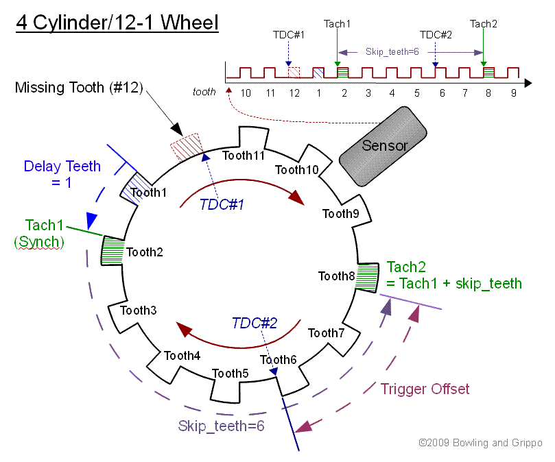
Tach1 is always where synch is declared by the ECU. It does this when:
For 4-stroke engines there are No_cylinder tach pulses over 720 degrees of crank rotation. Therefore:
Note: the similarly named user input 'Skip Pulses' (no_skip_pulses in the code) has nothing to do with tach pulses – do not change this variable when setting up an initial configuration.
Trigger_Offset is in negative crank degrees.
Note that Tach1 is an exact tooth signal edge in crank degrees from T1 (rising or falling edge, user defined by the input capture (IC) setting). TDC can occur at, or between, teeth (if the TDC occurs at the tooth edge, then the Trigger_Offset will be zero). While the tooth edge is sensed by the ECU, TDC is not sensed by the ECU, so the user must tell it where TDC is relative to the corresponding tach tooth by specifying Trigger_Offset.
For the next few examples we will assume the Trigger_Offset is zero (i.e. that tach tooth occurs exactly at TDC for a particular cylinder), then we will show the effects if it is not zero in the last examples.
For an even-fire engine, the same offset applies to all cylinders.
Note also that TDC1 can be any cylinder, but as far as the ECU is concerned, this is cylinder number 1, and subsequent cylinders are in firing order, not the cylinder numbering convention for your model of engine. TDC2 refers to the TDC that comes after the first TDC, not necessarily the TDC for cylinder #2. So whatever cylinder is selected for Tach 1 must have its coil and injector wired to the IGN1 and INJ1 pins on the ECU and trigger offset is referenced to this cylinder.
For example, if you engine's firing order is 1342, and cylinder #1 is #1 according to the ECU (i.e. it is the first cylinder to TDC after the missing tooth and delay teeth - see below), then:
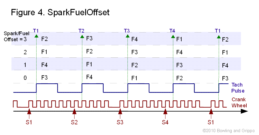
When Tach1 arrives, the ECU sets up the timing for dwell for coil 3 and spark in cylinder 3, which correspond to Tach3/ TDC 3. At the same time it opens Injector 3 (unless there is an InjStart delay, in which case it delays a specified number of degrees; or unless there is a SparkFuelOffset, in which case it picks another injector to open).
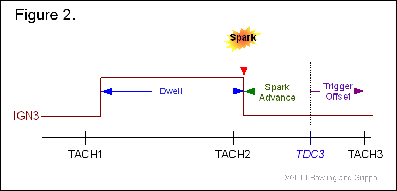
The main consideration here is the ECU must fit the dwell plus spark advance plus trigger offset inside 2 tach cycles at high rpm. To determine if this is possible for your combination of user settings, you have to decide the minimum amount of time you can dwell to get acceptable spark, then convert this to crank degrees at the maximum expected rpm and add the maximum expected spark table advance plus trigger offset.
|
The milliseconds per revolution is equal to 60000/rpm, because there are 60000 milliseconds in a minute. The revolutions per milliseconds is rpm/60000. Since one revolution is 360°, the degrees per milliseconds is rpm/166.7, (where 166.7 is 60000 millisec/rev ÷ 360°/rev). The degrees for dwell (which is in milliseconds) can then be calculated as:
|
This total amount of crank degrees must fit between Tach 1 and Tach 3, with a few degrees of slop for prediction error. If it does not fit within that time span, you will either get a short dwell or a spark at Tach 3 (0° advance). So move the Delay_Teeth and corresponding trigger offset until proper dwell is achieved. Since trigger offset can be a fraction of a tooth, adjust it exactly with a timing light. This is all shown in figure 2. below:
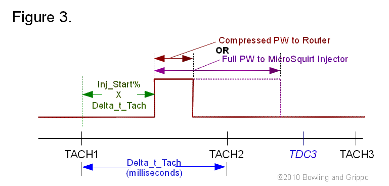
InjStart is a percentage (%) of one tach cycle for which the injection is delayed relative to the start of the tach cycle.
You can not delay the injection so much that the injection starts with less than 2 milliseconds remaining before the end of the tach cycle. This is because the router must receive the starting edge of the pulse width before the next tach cycle, and the 2 milliseconds allows for prediction error, interrupt latency and pulse width calculation time.
The 78% in the illustration below is just an example at a specific rpm. At low rpm you could reach 90% or more, at higher rpm less than 78%, but at high rpm fuel timing is less critical because fuel/ air mixing is much better. Likewise, Injector 2 covers most of the region from Tach2 to Tach3.
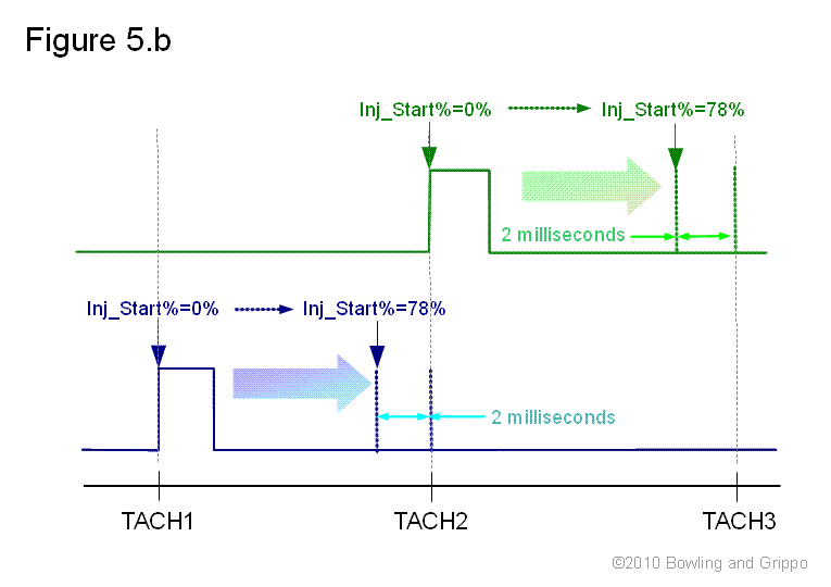
Figure 5.b shows the same configuration, but with SpkFuelOffset = 1, which is the same as swapping the injector wires for channels 1 and 2. Injector 1 can now be made to cover the Tach 2 to Tach 3 region and Injector 2 covers Tach 1 to Tach 2:
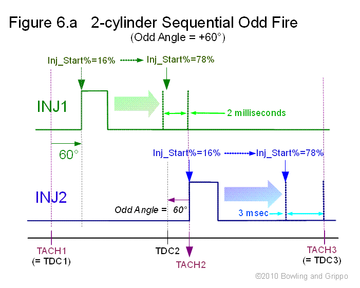
So, if the Odd_Angle offset (aka. OddAng in the code, Offset (advance) for Output #2 in the tuning software) is positive, meaning the offset is to be added to Ign 2, Inj 2 outputs to advance(+) rather than retard(-) relative to Ign 1, Inj 1, then InjStart can not be 0%. It can be entered as 0 in the tuning software, but the delay relative to cylinder 2 TDC will actually be:
as shown in the examples shown below.
So in order for the fuel to be injected at the same relative position in each cylinder, InjStart must be set to 16% or else Inj 1 will open immediately after TDC1, but Inj 2 is forced in the code to open 60 deg after TDC2 at the earliest.
Note that setting SpkFuelOffset = 1 will reverse the injections in the same manner as in Figure 5.b, but because of the Odd_Angle characteristics, it then may only be possible to find a start time that is only approximately equally distant from the respective TDCs for each cylinders.
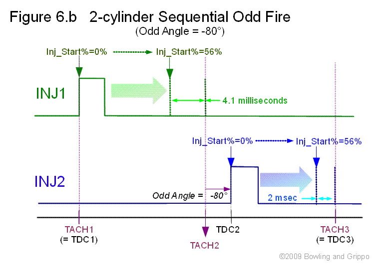
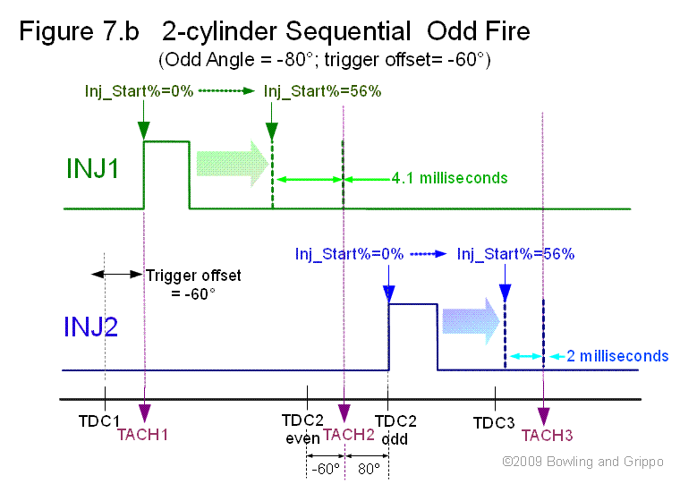
With a negative Odd_Angle, there is no problem with both injectors opening right after tach, but the range through which you can move the injection is limited to 56% before the 2 milliseconds before tach limit is reached on the second injector channel.
For an even-fire engine, trigger offset is defined as the difference in degrees between Tach n and TDCn.
For an odd-fire engine the same is true for Tach 1 and TDC1; for the pair that arrives next, the trigger offset in the code remains unchanged, but the Odd_Angle input, which defines the lead or lag of TDC for the second cylinder or cylinder bank relative to the first, is subtracted, so that the actual Injstart for the Odd_Angle pair is:
Because of the way the code is structured, InjStart is defined with respect to the tach pulse. This is the earliest that the fuel injection can start, and for the first Tach, TDC pair, InjStart = 0% means it starts immediately after the tach pulse is processed and the ignition and pulse width variables are calculated.
For the second tach, TDC pair, the same is true except that the Odd_Angle input (60 degrees in the example), converted to percentage (16%), is subtracted from InjStart, but the result is forced to be 0 or greater.
The example below (figure 7.a) shows how you can set up so that InjStart covers the same range relative to TDC1 and the actual TDC2. It is similar to the setup in Figure 6A, except now there is another 60 deg section due to trigger offset being -60 degrees.
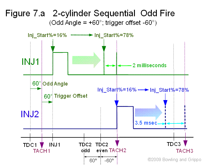
In the preceding, you could choose trigger offset = -30 deg and get similar results, with the 60 degrees|60 degrees segments becoming 30|60 for Inj1 and 60|30 for Inj2. Likewise, a trigger offset of -80 deg would give 80|60 for Inj1 and 60|80 for Inj2, but again the actual injector start times for both injectors would be the same for both relative to their TDCs.
Unfortunately, the same result is not possible for a negative Odd Angle, as can be seen in the example below (figure 7.b). Choosing InjStart = 0% means the earliest Inj2 can start is when TDC2 arrives, because the actual start = input start – (-80 degrees in percentage = 80°/(720°/2) = 22 %).
However, this value of InjStart causes Inj1 to start 60 degrees ATDC1, and increasing InjStart does not improve anything. So in this situation, the most equitable result is to minimize trigger offset, by either moving the sensor or using Delay_Teeth, or reverse the injector wiring.
Note that on most engines fuel timing, unlike ignition, does not require great precision. Timing the fuel shows marked improvements primarily if the timing is such that fuel is being injected when both the intake and exhaust valves are open (the overlap period near TDC between the exhaust/intake strokes). As long as the timing is moved enough to avoid this, further tuning is not critical.
Click here to see the Procedure for Configuring Dual Spark Wheel Parameters
| Preferred in this document: | Tuning Software: | Code: | INI: |
| No_Skip_Teeth | Skip Teeth | No_Skip_Teeth | No_Skip_Teeth |
| Delay_Teeth | Delay Teeth | Delay_Teeth | Delay_Teeth |
| SparkFuelOffset | Spark/Fuel Offset | spk_fuel_offset | spark_fuel_offset |
| InjStart | Injection Timing Delay | InjStart | InjStart |
| Trigger Offset | Trigger Offset | adv_offset | triggerOffset |
| Odd_Angle | Offset (advance) for Output #2 | OddAng | OddAng |
| →→→ | →→→ | →→→ | →→→ | →→→ | →→→→ | ↓↓ Under Construction ↓↓ | ←←← | ←←← | ←←← | ←←← | ←←← | ←←← |