MS-II Sequencer
MS-II Sequencer
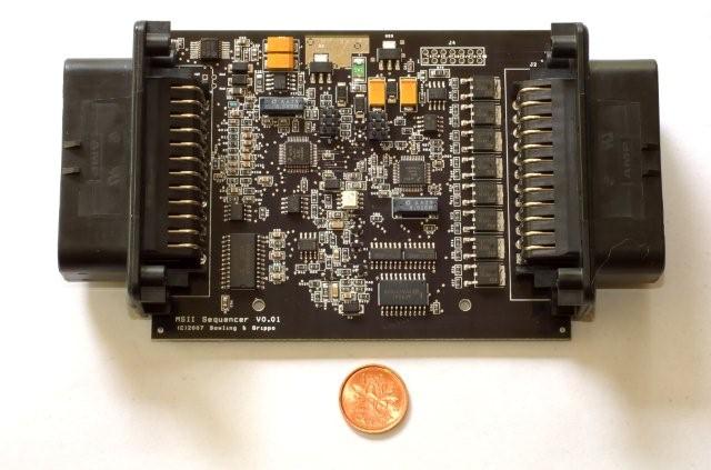
Bowling and Grippo are soon (likely early 2009) going to offer a sequential MicroSquirt®, called "MS-II Sequencer". The reason for doing this is that we have the infrastructure now for MicroSquirt®, all of the parts, harnesses, case, etc. And we have many users looking for sequential injection or coil-on-plug control (or both). As a result, it made sense to extend MicroSquirt® to generate sequential functionality (fuel injection timed to ignition order, and cylinder-by-cylinder injection and ignition tuning). The MS-II Sequencer™ case is the same as MicroSquirt®, except 4.8 inches (12.2 cm) long instead of 2.4" (6.1 cm). And we use the same end plates with the same cutout as MicroSquirt® (on both ends of the Sequencer), another cost savings since only one type of end plate is needed. By doing the Sequencer™ this way, we have a lot of cost savings which we will pass along in the resale price. Otherwise, it would have required a new extrusion, with all the associated costs having to be passed along.
The concept is the same as the external router board, including angle based spark and sequential outputs.
The price for the MS-II Sequencer™ has not been set yet. Initial estimates are that it will be a 35 - 40% increase over the cost of MicroSquirt® EFI controller, since there are roughly 35% more components, and the added harness assembly, Ampseal connectors, assembly cost, and enclosure, plus the extra cost for the aluminum and panel cutout for the second connector. Since MicroSquirt® retails for about $400, the estimated price is likely between $520 and $580. This could change somewhat, but is a reasonable ball-park figure. When pricing is finalized, it will be posted here.
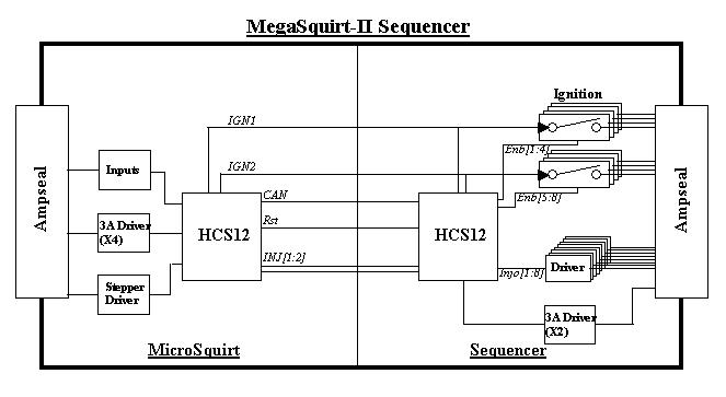
What we have done is extend the MicroSquirt® board and add another 35-pin Ampseal on the other end. We put on another 48-pin HCS12C64 (the same processor as MicroSquirt®) and communicate between the two processors using CAN.
The MicroSquirt® side is untouched, with the exception that the injector and ignition outputs are removed (now these are on the other side) and the stepper motor chip is put back in place. The VR inut circuit polarity is reversed compared to the V3 main board, just like MicroSquirt®.
The two injector and two ignition channels are fed over to the new processor, all it has to do is sequentially route the channels to up to 8 injector and 8 ignition outputs. The injectors are driven with the VND5N07 drivers (just like MicroSquirt) and the ignition is just TTL outputs (transistor-transistor logic; a TTL signal is defined as "low" when it is between 0.0 Volts and 0.8 Volts with respect to the ground terminal, and "high" when between it is between 2.0 Volts and 5.0 Volts) which can run coil per cylinder ignitions (COP & CNP).
The Sequencer™ maintains the ignition output accuracy at 2/3 of a microsecond by using external AND gates which are enabled by the sequencer (a.k.a "router") processor - these steer the two outputs to 8 different ones. Since we have two ignition outputs from MicroSquirt® EFI controller, the dwells can overlap and this is maintained on the Sequencer™.
For the injection, the sequence processor will measure (via input capture) the injector pulse width and simply pass to one of 8 outputs. We are using both injector outputs on MicroSquirt® to feed the sequencer processor. However, for high RPMs and long pulse widths, even with two outputs there may not be enough time. So the sequencer does "pulse width compression/expansion", where it scales the pulse width on the MicroSquirt® down, and on the sequencer side it will 'expand' it back out. By using a compression/expansion scheme we will lose some injector resolution, with the math is working out to ±12 microseconds resolution. The ignition channels (the critical ones!) is still 2/3 of a µsec resolution, the external AND gates control this.
The MS-II Sequencer™ controller contains a second HCS12 in the router section - it is a two-chip setup. We refer to the first HCS12 processor as the 'primary' processor - it runs the same code as MS-II/MicroSquirt. We will call the second HCS12 processor the 'router' processor. A CAN message from the primary processor to the router processor configures number of cylinders, as well as wasted/sequential. Two injection and two ignition channels (a.k.a. MicroSquirt) are routed by the second processor. Injection is compressed/expanded (see below) to yield a ±6 microsecond resolution and allow for high RPM with long pulse widths.
The ignition is a bit more complicated, with the addition of a CPLD (Complex Programmable Logic Device). The MS-II™ primary processor has the capability of spark resolution at 2/3 of a microsecond, and we want to maintain this if at all possible. We have seen that with some really high-revving engines (13K+) with MicroSquirt® that 1° control makes measurable power difference at high speed.
With MicroSquirt® code running on the primary processor, there are two ignition output channels that ping-pong back and forth. These two channels, via the Altera CPLD, get routed to one of 8 outputs, using two identical 2-to-8 decoders, one for each ignition channel.
From the second HCS12 router processor there are eight control signals that go to the CPLD.
Here are some note on how this works:
The CPLD has 64 logic elements (LE), all of the router logic only chewed up 12 LE in the Quartus tools, so we have a lot more to use if we want.
The CPLD is a 3.3V device from the MAX3000 family. These are very inexpensive (in the $2 range), but some tricks are required to interface with 5V logic from the two HCS12 processors. First, there is a 3.3V supply for the CPLD, a LT1117 (Linear Tech) handles this small amount of current. Next, logic outputs are 3.3V, but we need TTL-level signals for the ignition outputs, so we are using a 5V buffer chip. This chip is TTL logic level so a logic high of 3.3V input is considered a logic high for TTL 5V - CMOS inputs would not work.
The ignition and control lines from the two HCS12 processors are 5V, and just hooking them up to the CPLD would not be good. The CPLD has internal body diodes that will sink/source current if the input is below 0 volts or above 3.3V. Feeding 5V into the 3.3V input would turn the body diodes on and without any current limiting the Altera would overheat from the free-flowing current. So, the two ignition channels from the MS-II processor route through series resistors to limit current, and to keep the rise times short.
Now, the 8 control lines from the router processor also need limiting as well. But - there is simply no more room left on the board for 8 resistors. So, we are using a little trick. The HCS12 processor ports can be configured as inputs or outputs, and there are internal 50K pullup resistors (really current sources). So what is done is to run the HCS12 in "open-drain" mode. What is done is to set the output register to zero. Next, the pull ups are enabled. Then the data-direction register on the HCS12 is used to control the output. For a logic zero, the port is configured as an output, and since there is a zero in the data register the output is a zero. For a logic one, the data direction register sets the processor port as an *input*, so there is no drive - but the pullup resistors raise the output port to 5V. The pullup resistors limit the current flowing into the CPLD, and we are good.
Note that with the CPLD, it is possible to not use two HCS12 chips but one HCS12 chip in a bigger package and dedicate 8 signals to control the router. The two-chip setup right now is for us to take advantage of the huge stockpile of HCS12 chips we have on hand. We probably will later re-layout to a larger package (and XGATE compatible). But the takeaway here is that the CPLD allows us to take two timer channels and maintain the timing accuracy to eight outputs, and easily switch between wasted and COP.
There are two additional control lines from the router processor to the CPLD used for "spares" (any good designer will take all unused processor lines and route to an FPGA/CPLD for later use - programmable logic are useful creatures for hardware changes later on). And we have gobbled one of the spares up - we realized at out of reset the router processor will take a small amount of time to set the port up correctly, but during this time the CPLD can float to any routing configuration. So we are using a spare line as an CPLD output enable such that the 8 ignition outputs will come up disabled. The spare line has an external pull up to force a logic 1 at power up, and we set logic zero to enable the outputs of the CPLD.
In reality good enough for pretty much anyone's install (at 1 millisecond pulse width the ±12 microsecond resolution is 1.2%, and at 2 millisecond it is 0.6%, so it quickly becomes irrelevant - especially when no one can even measure AFR better than 2% or so). If the ±12µsec is not good enough for some users, then we have another software encoding scheme with the two injector channels that will maintain full precision.
What we would do in that case is to use both injector channels at the same time to convey the pulse width:
Pulse Width = Inj1 / 10 + Inj2(fractional(PW)*1000)
The sequencer board side is:
Pulse Width = Inj1 * 10 + Inj2/1000
For example, with a 12.32 millisecond pulse width:
This way the injector precision is maintained and there is always enough time to signal the pulse width between pulses at high RPM.
The sequencer has a CAN bootloader so that one can upload the code to a CAN device on the net. The MegaSquirt-II™ 'primary' processor programming will be version 3.00, but this code will also work on a standard MS-II™. Al is hard at work on the sequencing processor. Right now you can run Dual Spark with 8 cylinders, but it just cycle between 2 outputs. The sequencer will cycle these 2 outputs into 8 outputs. On the MS-II side Al has already added fuel and spark trims for 8 cylinders.
The MS-II Sequencer™ controller has a header (J4) on the board that is targeted for an upcoming "feedback" board which will provide:
You will notice on the header that there are two ADC channels routed to the header, the O2 and the spare ADC channel (for knock). And there are several signals routing to the Ampseal. So the user will simply plug in the board and wire the wideband and knock sensor to the Ampseal connector and be ready to go. There is also the CAN interface so that communications to this board will be seamless.
The wideband circuit is a simplified version of the PWC, but it will perform the analytical wideband calculations based on input fuel type and sensor sensitivities of O2, H2, and CO.
Also, this board will have the new Cortex-M3 processor from ST, the STM32. It is 70 MHz, 90 MIPs, with hardware divide, fast enough to keep up with the calculations in real time.
The knock circuit is a band pass filter with adjustable center frequency, with a sample and hold with windowing.