
A.UltraMegaSquirt, the next generation fuel injection and ignition controller from Bruce Bowling and Al Grippo, is based on the recently announced Freescale (né Motorola) Coldfire MCF5234 processor. Work is currently moving forward at full speed on UltraMegaSquirt, however an announcement on UMS availability is not imminent.
When MegaSquirt® was started almost three years ago, the best bang for the money was the HC08 family (also Atmel and Microchip). In three years, looking at the next step range of processors, the family that stands out is the ColdFire®. UltraMegaSquirt uses the recently announced ColdFire® MCF5234 from this family of processors.
UltraMegaSquirt will have the following enhancements over MegaSquirt:
| Specification | MC68HC908
(MegaSquirt) | ColdFire® MCF5234
(UltraMegaSquirt) |
| CPU core | 8 bit | 32 bit |
| Speed | 8 MHz | 100 MHz |
| Flash | 32 Kbytes | 2 bank SDRAM controller |
| User RAM | 512 bytes | 64K SRAM |
| Temperature Range | -40şC to 85şC | -40şC to 85şC |
| Power | 5 volts | 5 volts |
2) Connector: The current MegaSquirt® DB37 connector works well, with very few reported failures. However it can be a little tedious to solder large wires to the solder cups. Bruce and Al have shook the trees for connector suppliers, and UltraMegaSquirt uses the AmpSeal series of connectors - these are sealed automotive-grade connectors which can handle up to 17 amps per pin, and are submersible!
3) Automotive-grade: Everything is automotive-grade, including processor, connector, etc.
4) Existing software: The goal of choosing a processor is to try to keep the current established code operational. With the ColdFire® MCF5234, it is very easy to modify existing assembly code for this processor - it amounts to about a two hour effort, without taking advantage of the ColdFire® MCF5234 architecture. And, if people want to code in C, there is a good GNU port available, as well as Metrowerks Codewarrior. See below.
5) 12 x 12 Tuning tables: For Volumetric Efficiency (VE) table (versus MegaSquirt® 8 x 8), 12 x 12 for Air Fuel Ratio (AFR) table, and 12 x 12 for Spark Advance table. Note that UltraMegaSquirt allows the use of two independent VE/AFR tables, for operation in 'dual table' mode.
6) Stepper motor IAC 'fast idle' control: for common EFI idle control motors, as well as support for MegaSquirt's FIdle valve control.
7) Ignition: UltraMegaSquirt code has the ability to control ignition. Initial release supports 1 coil/distributor. Later releases will support coil on plug, knock sensor feedback, etc.
8) Dual Wideband O2 feedback control: It is quite clear that people want to tune to mixtures other than 14.7:1. UltraMegaSquirt incorporates the circuitry to handle up to two Bosch LSU4 wide band oxygen sensors is on-board. Al and Bruce spent thousands of dollars on good wideband testers, including the coveted ETAS LA3 Lambda Meter. They set up a WBO2 flow bench in order to measure the WB circuit and compare against the LA3. Controlling the Bosch LSU4 sensor is quite different compared to the wide band NTK L1H1 unit, especially the heater circuit. They have been able to get real data comparisons with real test equipment, which has helped work out things like feedback transient response, etc. All of this knowledge has been incorporated into UltraMegaSquirt.
9) Turbo Wastegate/ Nitrous Activation: UltraMegaSquirt has built in support for controlling an electric turbocharger wastegate or nitrous oxide solenoids
10) Form factor: The UltraMegaSquirt enclosure is smaller than the current MegaSquirt® box. To do this UltraMegaSquirt had to go to surface mount for all components.
11) Cost: The cost is just a little more than the MegaSquirt® setup. The AmpSeal connector is quite expensive (~$20.00) but the other components are roughly the same cost as the current MegaSquirt® equivalents.
A. As of May 2004, Al is working on software and is testing specific circuits of the UMS I/O.
Right now, there are 12 power outputs (excluding stepper motor drive and some general purpose outputs). These outputs are assigned to the function that the end user wants. For instance, if someone wants all 12 to be fuel injector outputs, then the switch fabric is set for this configuration. If someone wants 8 for injectors and 4 for wasted spark, then they set the fabric up for this. If someone wants 8 outputs for sequential injection, then the switch is set for this. If someone wants 12 outputs that just turn on solenoids (i.e. transmission), then the fabric is set to do this. If someone wants to run EDIS, then two of the outputs are defined for this function.
Al has also been finishing up the embedded code. Everything is in there for calculation of fuel and spark which encompasses all of the MS embedded code variants plus some nice additions. For instance, the code has full spark dwell control and a predictor/corrector algorithm for ignition. The code has VE and AFR target tables all with dual table capability. Full stepper idle control is also there.
Bruce is preparing the schematics, etc. With the fuel/spark code developed, there is a whole other part of the system to be developed - the routing and "switch fabric". Since the UMS outputs are multi-purpose, they can be defined via software for any function on the fly. The whole infrastructure for this (i.e. crosspoint switching, etc) needs to be implemented. This is the next step.
If a channel is defined as an ignition channel, then it is capable of directly controlling dwell. Same goes for a channel defined for FI control - it will handle flyback and damping for PWM current limit.
So you see the idea - there are two "parts" to UMS - one that performs the fuel calculations, ignition timing, activation of general purpose outputs, etc, and the other that routes and switches the outputs.
12 outputs were chosen simply because of the number of connectors left on the Amp connector, but this number is not set in stone as of yet. And, something I failed to mention in the last post is that UMS will use CAN (Controller-Area Network) as a major part of the system. What this allows for is the capability of cascading multiple UMS boards together, controlled by one unit and rest as slave devices. It only makes sense to utilize CAN as a mechanism for inter-system communications. For instance, once a UMS box reads the value of, say the coolant sensor, then this data is available in real-time on the CAN bus, in case another system requires the same information.
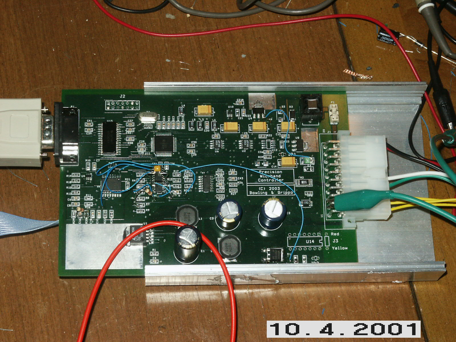
Bruce has been working on the WB02 part of the design, called the Precision Wideband Controller (PWC). He has a working board in which he is verifying proper calibration relative to different test gas/concentrations. Bruce and Al ended up purchasing a 5-gas Horiba meter directly from Horiba, which along with the use of primary gas standards for test gases lets them know exactly what the sensor sees.
Bruce is also verifying proper heater control (via PID loop) - this is very important to get correct (using the Etas LA3 as a benchmark). When he has everything buttoned up in a complete form, he will release all the information.
In his testing, Bruce has found out that if you have enough adjustability in both heater control and bandwidth in the pump (current) circuit, any of the UEGO sensors can be run. Even in NGKs latest patents, they recommend variable heater control based on Ri measurement over the constant-current heater control method - it makes sense, in that exhaust gas temperature is no where near constant over the engine's normal operating range.
The original goal was to have everything on one board - but take a look at the image of the WB board below, you will see that the WB circuit takes up a bit of PCB real estate, so it may need to be separate.
But, there are some specifications which Bruce and Al are in the process of determining with given hardware (for instance, how many user I/O vs. available pins on connector, etc) so there are specifics which will not be released yet.
A. The Coldfire® is a totally awesome processor. UltraMegaSquirt uses the MCF5234 processor from Motorola's ColdFire® family of automotive grade processors (Motorola Semiconductor is now being called Freescale Semiconductor). This inexpensive controller was designed for networked and stand-alone complex real-time control applications such as industrial control, manufacturing equipment and robotics. It is ideal for a fuel injection and ignition controller.

The MCF5234, a highly-integrated 100Mhz 32-bit microcontroller, combines high-performance data manipulation capabilities with powerful peripheral subsystems. The MCU is built up from standard modules that interface through a common intermodule bus (IMB).
The MCU incorporates a 32-bit CPU (CPU32), a system integration module (SIM), a queued serial module (QSM), and a 64 KB internal static RAM (SRAM) module, with a 16-channel eTPU with 6 KB of SRAM.
The ColdFire® MCF5234 microcontroller unit (MCU) is a 32-bit device with outstanding on-chip peripherals including:
The ColdFire® MCF5234 has full 32-bit data paths throughout. The inclusion of a Phase Locked Loop (PLL) circuit allows power consumption and performance to be adjusted.
The enhanced time processor unit (eTPU) is a 32 bit co-processor with it’s own core and memory system, allowing it to perform I/O management independently of the CPU. The eTPU is essentially a microcontroller all by itself! The eTPU of the MCF5234 is a co-processor with 16 channels, dedicated to performing high speed complex timing and I/O, releasing the CPU for other tasks.
Note how this is very convenient for a fuel injection controller, which needs to both:
The eTPU is ideal for motor control, serial communications, engine control, and dynamic system control. In fact, it was specifically designed for the complex I/O management required for spark and fuel control in automotive engines. This allows the use of much of the work Al put into the code when designing the original EFI332, which was based on the MC68332 processor. To see how far we've come, check out this:
| Specification | MC68332 | MCF5234 |
| System Clock | 16 MHz | 100 Mhz |
| Performance | 4.8 MIPS | 96 MIPS |
| DMA | 0 | 4 channel |
| SRAM/Cache | 2K/O | 64K/8K |
| SDRAM controller | 0 | 1 |
| UART/SCI | 1 | 3 |
| QSPI | 1 | 1 |
| I˛C | 0 | 1 |
| CAN | 0 | 1 |
| Timers | 16 channel TPU | 16 channel eTPU 4 channel 32-bit timer 4 channel PIT |
There are many advantages with the new eTPU:
The development of eTPU functions is supported by a C compiler, simulator, and debugger. Built in eTPU functions include:
UltraMegaSquirt uses CAN (controller-area network) as a 1 Mbyte/sec bus, in order to attach external peripherals (i.e., PWC, dash boards, more UltraMegaSquirt boxes, etc) in multi-drop fashion without having a bunch of parallel wire connections. In fact, UltraMegaSquirt interfaces with the wideband circuit via CAN, due to the fact that the wideband circuit has additional signals (like WM enable, WB good/bad, WB un-calibrated, etc) needed for real time mixture control.
A. There is still lots to do on this to make it right.
Before everyone asks for circuits, etc - right now the schematics are in a notebook and the subsections are breadboarded - there is no complete schematics right now, but Bruce is working on them. This will change shortly.
What Bruce and Al want to do is get the function pin assignments and memory maps out to the world early so that people who want to start making code they can do so (either porting existing code or making new code). The Metrowerks simulator is a very nice tool and is a good thing to test code before having the hardware.
A. The plan is to have all IC's resistors, caps, etc, SMD. Using 1206 SMD footprint (the plan) it is not hard to solder at all.
The plan is to look at having a manufacturer do all of the "hard" soldering (like processor and other chips) and let the user solder on things like connectors and the like. We want the success rate to be high (and frustration rate low), so having some of the parts mounted will really help. But, it will still be a kit.
A. Surface mounted technology uses surface mounted devices (SMD) that solder directly to the PCB using flat 'gull wing' legs (or J-leads) and solder pads rather than long wire leads and through holes. There is a more SMT info here.
A. Surface mount device (SMD) component sizes are usually stated in terms of their approximate size in either inches or millimeters. The footprint (size) of flat chips is identified by a 4-digit size code. The first two digits in the size code refer to the length, and the second two digits refer to the width.
In the USA, this 4-digit size code is measured in hundredths of an inch. Outside the USA, the size code may be either tenths of a millimeter or inches. This can cause confusion, so it is important to verify whether the size code is in metric or inches. For example, if the first two digits in the size code are 12, then the length of the flat chip is .12". However, if the size code is metric, the 12 would equal 1.2mm. For example, a ceramic SMD capacitor (or resistor) which is 0.126 inch (3.2mm) long by 0.063 (1.6mm) wide is called a "1206" size. There are numerous exceptions, however. For example, SMD tantalum capacitors are usually defined by their size in tenths of a millimeter, so a 1206 tantalum is called a 3216 (3.2 mm long by 1.6 mm wide).
The thickness (T) of the package is not included in the 4-digit size code. You must refer to the actual manufacturer's data sheet to get information regarding thickness. Some versions have an "L" version for low profile. An 'A' tantalum (3216) is 1.6 mm high while the AL is 1.2 mm high. All L versions have a maximum height of 1.2 mm, while non-L tantalums can go as high as 2.9 mm. The "L" versions have their own letter designation. Manufacturers don´t always follow the standard letter designations, especially with the low profile versions.
Here are the most common size codes for capacitors and resistors:
| Inch | Metric | Inch | Metric |
| 0402 | 1005* | .04" x .02" | 1.0 x 0.5mm |
| 0504 | 1210* | .05" x .04" | 1.2 x 1.0mm |
| 0603 | 1508 | .06" x .03" | 1.5 x 0.8mm |
| 0805 | 2012 | .08" x .05" | 2.0 x 1.2mm |
| 1005* | 2512 | .10" x .05" | 2.5 x 1.2mm |
| 1206 | 3216 | .12" x .06" | 3.2 x 1.6mm |
| 1210* | 3225 | .12" x .10" | 3.2 x 2.5mm |
| 1812 | 4532 | .18" x .12" | 4.5 x 3.2mm |
| 2225 | 5664 | .22" x .25" | 5.6 x 6.4mm |
| 2512 | 6432 | .25" x .12" | 6.4 x 3.2mm |
| * Caution: Overlapping size codes. Metric appears same as inches. | |||